- Define battery-module and pack weight, center of gravity, electrical state, permitted contact areas and no-pressure areas before design.
- Give the tooling a clearly defined primary load path. Do not use weak housing areas, connectors or cooling components as supports.
- During turning and positioning, control center-of-gravity changes, orientation holding and approach to fixtures.
- Permit release only after the workpiece is supported and load transfer is complete. Also verify responses to air loss, power loss and identification faults.
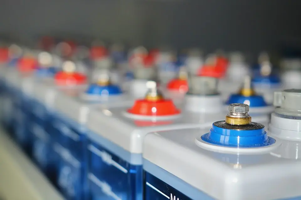
EV battery modules and packs may include cooling plates, high-voltage connectors, sealing surfaces and locating features. Handling must provide both load support and product protection. Begin with permitted contact areas, define retention during flipping, placement detection and abnormal responses, and verify load-transfer and release conditions at each stage.
01Define product state and handling requirements
First distinguish empty housings, assemblies in progress, completed assemblies and energized test states. Then record whether cells are present or the product is energized, SOC management, weight and center-of-gravity tolerances, housing version, coolant condition, connector protection, cleanliness and environmental requirements.
Product engineering, process and equipment personnel should jointly mark primary load-bearing points, permitted contact areas, locating points, no-pressure areas, sealing surfaces, cooling plates, vent or pressure-relief areas, and high- and low-voltage interfaces. Design the gripper from this product information; do not infer load-bearing points from appearance.
02Five main risk categories
- Dropped or slipping loads: insufficient gripping, identification errors, loss of energy or operating impacts can destabilize the workpiece.
- Structural damage: weak housing contact areas, excessive local pressure or changing load paths during turning.
- Electrical and interface damage: impact on high-voltage connectors, harnesses, sensing interfaces or insulation.
- Abnormal product condition: unusual temperature, visible damage, leakage or other conditions that prevent normal handling.
- Interference: large workpieces can obscure visibility or enter vehicle-body, fixture and operator spaces during turning or assembly.
03Establish the primary load path
Select support lifting, mechanical clamping, internal expansion, attachment to lifting points or a combination based on the product structure. Check primary load-bearing locations, measures against lateral slip and rotation, and whether effective support remains after cylinder, suction-cup or sensor failure.
For mechanical clamping, verify clamping force, friction variation, local stress and deformation. For support lifting, verify resistance to sliding out during acceleration, deceleration and flipping. Use vacuum only where the surface and product requirements permit it, and verify sealing, area, retention and surface protection. A single unmonitored friction condition should not be the sole safety basis for battery workpieces.
04Control center of gravity and orientation during turning
Locate the flip axis relative to the combined center of gravity of the battery pack and gripper to control operator effort and braking demand. Calculate and test loads at the starting, intermediate and final angles, checking the gripper, rotary mechanism, brakes and locking capacity. Also check the full-angle envelope of hoses, cables and workpiece edges.
Provide mechanical or otherwise verified locating datums for final orientations needed for adhesive application, inspection or assembly. Avoid approaching tooling by visual angle estimation alone, which can cause interference or impact.
05Separate coarse guidance from precision location
The manipulator supports the weight and provides broad guidance; precision location is supplied by tooling guides, locating pins, floating mechanisms or dedicated centering structures. Preserve visibility of critical clearances in the gripper layout so operators do not have to judge seating solely by pushing force when the workpiece blocks the view.
When approaching the vehicle body or pallet tooling, reduce motion inertia and constrain unnecessary degrees of freedom. Check protection of connectors, coolant interfaces, studs and sealing surfaces. Do not use the manipulator to force a misaligned workpiece into position.
06State conditions for gripping, lifting and release
| Action | States to verify | Conditions that inhibit motion |
|---|---|---|
| Clamping / vacuum gripping | The vehicle model matches the fixture, the contact position is correct, and the workpiece is allowed to be transported | Identification mismatch, excessive position error or abnormal workpiece condition |
| Lifting | Locked in place, pressure/vacuum normal, key supports effective | Any key status is missing or contradictory |
| Turning | The load has left the material rack, the orientation mechanism is locked, and the path is cleared. | Continued contact with fixtures or an occupied swept area |
| Release | The target tooling is in place, the workpiece is supported, and the load is transferred | Suspended load, unverified support or abnormal signals |
Use mutually supporting state evidence for motion permissions. Gripper height indicates only position, and tooling in position does not prove load transfer is complete. Select position, contact, load, pressure, vacuum or other detection according to risk to support clamping, lifting and release separately.
07Abnormal workpieces and utility loss
Battery workpieces showing visible damage, deformation, leakage, abnormal temperature or failed identification must enter the isolation and reporting process rather than continuing at the normal cycle. On air loss, power loss, insufficient vacuum, conflicting sensors or communication loss, the equipment must follow its defined strategy to hold, stop, alarm and place the load under control.
Restoration of utilities must not automatically resume the interrupted movement. First check workpiece position, gripper state and personnel areas, then recover through the controlled procedure or transfer the workpiece to a safe support.
08Verify normal and worst-case conditions
- The heaviest, largest, most unfavorable center of gravity and surface tolerance workpieces.
- Complete gripping, lifting, translation, flipping, positioning and release cycle.
- Tooling changeover, incorrect models and partially locked interfaces.
- Air pressure drop, loss of compressed air, power outage, vacuum leakage and sensor abnormality.
- Continuous cycles at the specified production rate and durability of critical components.
- Manual rescue, support, unloading and recovery steps after an abnormality.
09Standards and project application
GB 38031—2025, Safety Requirements for Power Batteries for Electric Vehicles, took effect on July 1, 2026; AQ 7017—2025, Safety Specification for Lithium-Ion Battery Production, is a current industry standard. These standards show that traction-battery products and production safety require systematic management, but they do not replace the structural design and risk validation required for a specific handling tool. Project requirements must still be defined from the equipment classification, factory rules, and all other applicable standards.
Use product state and permitted load-bearing areas as inputs to the battery handling design, implementing the primary load path, motion permissions and abnormal responses for each model and station. Verify with actual workpieces under worst-case conditions and produce traceable configuration and acceptance records.