- Survey seven areas on an existing automotive line: workpieces, process, space, structure, utilities, controls and safety.
- Measure pickup and placement locations as well as the dynamic envelope of tooling and workpieces, machine doors and fixtures.
- Near robots, conveyors or welders, define status signals, emergency-stop scope and construction permits before installation.
- Hidden services and load-bearing conditions require detection, inspection or structural review records. Unverified conditions must not be used as a basis for installation.
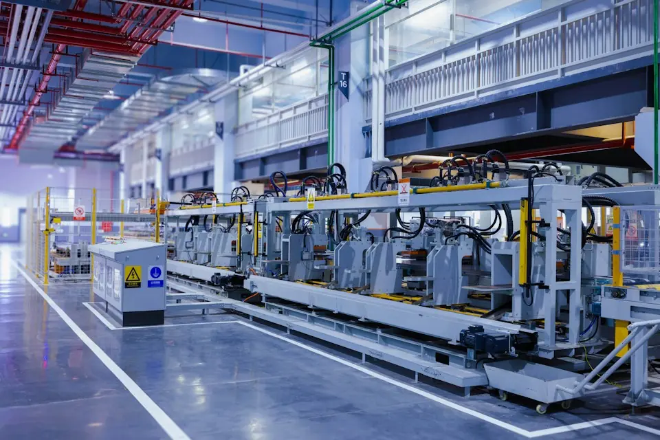
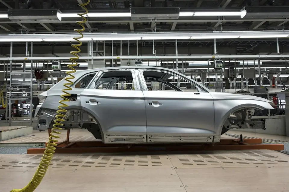
Tooling, conveyors, robots, guards and aisles are tightly integrated on existing automotive lines. Before adding equipment, organize photos, measurements, motion timing and interface information into a consistent as-is record for payload selection, layout design, installation and acceptance.
01Workpiece requirements
- All vehicle models or part models, as well as future planned compatible ranges.
- Weight, dimensions, tolerances, center of gravity and worst combinations.
- Permitted gripping, vacuum, internal-expansion or support locations, and no-pressure or no-scratch areas.
- Incoming orientation, placement variation, packaging and bin configuration.
- Whether there is oil, water, dust, protective film or curvature changes on the surface of the finished product.
Workpiece information must include both weight and load-transfer conditions. Even at the same weight, doors, seats, battery trays and tires differ in center of gravity, permissible contact areas and handling movements. Use these differences to determine the end gripper and equipment load.
02Process requirements: the complete cycle
Record the full cycle: pickup location, gripping direction, lifting height, path, flipping, placement datum, release and return. Also identify the state of machine doors, locating pins, clamps, lift tables, turntables, conveyor pallets and robots at each stage.
Measure the complete cycle and record shift output, operating frequency, continuous operating duration and changeover frequency. Include existing detours, waiting and secondary adjustments as a basis for process improvement and assessment of the new design.
03Space requirements: dynamic envelopes
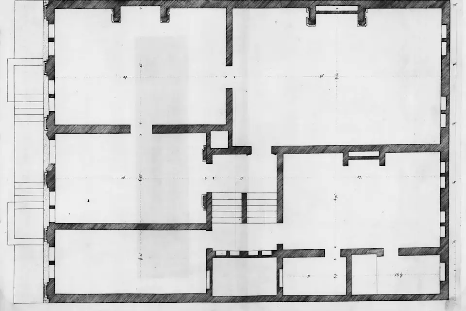
On the plan, mark pick and place coordinates, equipment outlines, columns, walls, guards, racks, personnel aisles and forklift routes. Add elevations showing pick and place heights, obstacle-clearance heights, overhead beams, cable trays, ducts, lighting, sprinklers and door-opening envelopes.
Include the gripper and largest workpiece outlines in the space check. For loaded travel with doors, headliners or battery trays, check swept envelopes at different orientations and preserve space for maintenance, abnormal withdrawal and operator movements.
04Structural requirements: floor and overhead supports
| Installation type | Required checks | Supporting information |
|---|---|---|
| Column-mounted | Concrete thickness, strength, cracks, steel bars, trenches and underground pipelines | Civil drawings, detection results and foundation assessment |
| Overhead-mounted | Beam/column sections, materials, connections, existing loads and vibration | Steel structure drawings, structural calculations or review opinions |
| Rail-mounted | Suspension points, end stops, track level and maintenance access | Suspension-point layout, track and support design |
| Mobile | Ground level, slope, joints, load-bearing and fixed positions | Relocation route and setup inspection requirements |
The equipment supplier provides applied loads and mounting conditions as inputs to foundation or building-structure review. Competent personnel must verify load-bearing capacity using the site structural information. Equipment specifications cannot replace that conclusion.
05Air, electrical and service connections
- Air supply: connection points, dynamic pressure, available flow, pipe diameter, filtration, drying, drainage and other major air users.
- Electrical supply: voltage, capacity, grounding, isolation points and requirements for pumps, sensors, identification and controls.
- Service routing: hose, cable and carrier mounting, bend radii, travel and abrasion protection.
- Environment: temperature, dust, welding slag, oil mist, cleaning fluids, strong light, magnetic fields and noise.
06Adjacent equipment and control interfaces
List the timing relationships among robots, welders, presses, conveyors, lift tables, turntables, locating fixtures and safety doors. The interface list must identify who supplies the signals for permission to pick, permission to place, workpiece in position and gripper withdrawn, and define safe states for communication loss or conflicting signals.
When a manually operated pneumatic industrial manipulator shares space with automatic equipment, use layout, travel limits, sequencing or isolation to control intersections between the manipulator's swept area and the motion zones of robots and tooling.
07Installation and production arrangements
- Available shutdown windows and night or weekend work schedules.
- Permits for hot work, work at height, lifting, drilling and temporary electrical supplies.
- Construction area isolation, material move-in routes and lifting conditions.
- Underground pipeline identification, dust and chip protection, and completion cleaning.
- Responsibility for production release and the first-piece verification procedure.
08Existing automotive line survey checklist
| Category | Required information | Records |
|---|---|---|
| Workpiece | Model, weight, dimensions, center of gravity, contact area | Parameter table and sample photos |
| Process | Complete motion sequence, cycle time, changeovers, and abnormal conditions | Flowchart or video |
| Layout | Plans, elevations, dynamic envelopes and access routes | As-is drawings with dimensional datums |
| Structure | Foundation or steel structure conditions | Drawings, inspection or review records |
| Utilities | Air, electrical and vacuum supplies, including capacity during operation | Interface points and measurement records |
| Controls | Adjacent equipment states and interlock scope | Interface list and sequence diagram |
| Safety | Passage, emergency stop, isolation and abnormal handling | Risk review record |
| Installation | Shutdown, permits, equipment access and production restart | Work schedule and responsibility list |
After the survey, include equipment load, mounting method, gripper concept, installation interfaces and acceptance items in the technical agreement, each supported by as-is drawings, measurement records and review documents. Schedule work involving hidden conditions only after the relevant checks are complete.