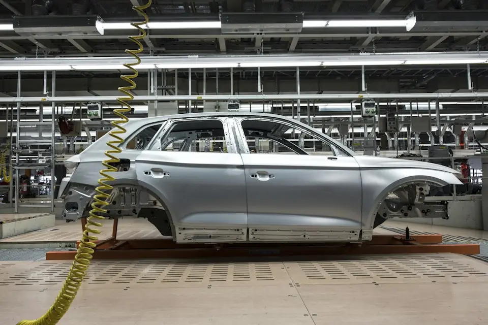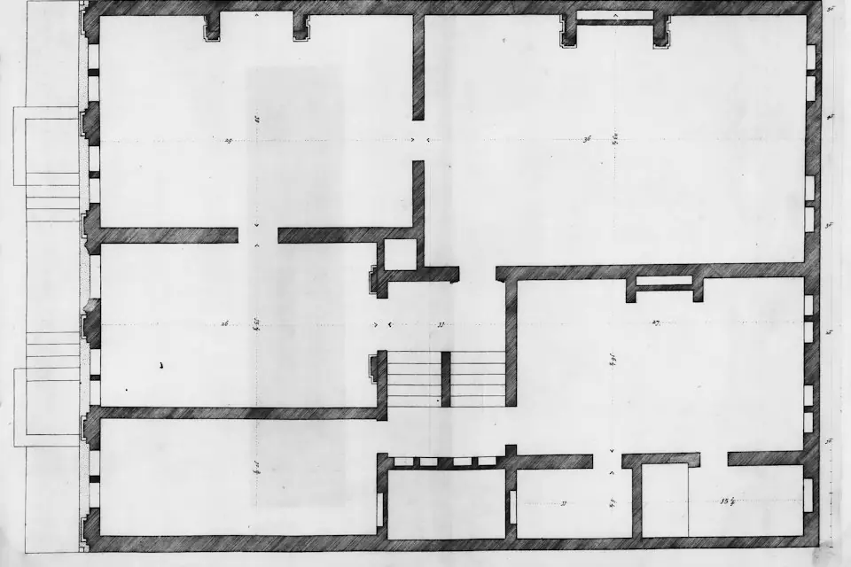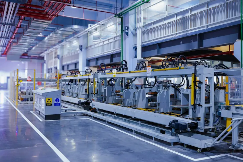
- For an existing-line retrofit, first measure the current process, motion paths and fixed facilities, then determine the equipment location and configuration.
- Projects generally follow six stages: site survey → process modeling → design review → interface preparation → installation and commissioning → workpiece verification.
- Common constraints involve foundations, overhead structures, swept space, air and electrical connections, shutdown windows and safety interlocks.
- Acceptance covers the complete cycle time, abnormal-event recovery, operating feel and maintenance access, with records of loaded operation.
Adding a pneumatic industrial manipulator to an existing line requires a fresh check of the working space for people, workpieces, tooling and equipment. Where documentation is incomplete, equipment locations are fixed, shutdown windows are short or buried services are unknown, complete site measurements and interface checks first. Then schedule prefabrication, installation and loaded verification to integrate the new equipment with the existing process.
01Assessing retrofit suitability
Candidate stations include repetitive lifting or supporting tasks with relatively well-defined pick and place points. Workpieces need suitable areas for clamping, suction, internal expansion or support; the cycle must allow gripping, moving and release; and the site must support floor mounting or overhead suspension.
Where incoming orientation varies, position fluctuates substantially, movements overlap extensively with high-speed automatic equipment or the cycle approaches fully automated handling requirements, compare pneumatic industrial manipulators, robots, intelligent lifting systems and dedicated machines against the actual task.
02Six stages of an existing-line retrofit
1. Site survey and baseline documentation
Survey workpieces and motions, site space and mounting interfaces separately. Workpiece data includes weight, dimensions, center of gravity, contact surfaces, orientation, heights and frequency. Space data includes equipment, racks, guards, columns, services, aisles and operator positions. Interface data includes the foundation, overhead steelwork, air supply, power and controls. Include measurement datums in photos and retain the source of key dimensions.
2. Model the process movements
Break the full cycle into approach, gripping, confirmation, lifting, transfer, flipping, positioning, placement, release and return. At each stage, add the workpiece and gripper outlines and check both static space and the swept motion envelope.
3. Review the design and installation type
Compare column-mounted, overhead, rail-mounted and mobile arrangements against the foundation and workstation conditions. During design review, check load, radius, stroke, gripper weight, structural capacity, operator positions, interference and abnormal withdrawal paths together.
4. Interface construction and prefabrication
Bases, brackets, grippers and piping assemblies can be prefabricated against verified interfaces. Before installation, identify buried services in drilling areas, review suspension structures, verify air quality and flow, and establish shutdown, energy-isolation and work-permit arrangements.
5. Install and commission without load, then at low load
Commissioning begins with checks of anchoring, leveling, rotational stops, pneumatic circuits and controls, followed by unloaded motions. Then add load gradually under low-risk conditions, checking balance, brakes, clamping, vacuum or mechanical retention. Do not proceed directly to continuous full-load operation before these checks are complete.
6. Verify workpiece cycles and abnormal conditions
Verification with actual workpieces covers normal, heaviest, largest and worst-center-of-gravity variants. Record complete cycle time, repeat positioning, changeovers and operating feel. Also rehearse responses to falling air pressure, insufficient vacuum, identification errors and loads not yet placed on their supports.
03Comparing installation types
| Installation type | Suitable applications | Existing-line constraints |
|---|---|---|
| Column-mounted | Single workstation or adjacent workstations, foundation can be arranged on the ground | Floor capacity, buried services, forklift routes and pedestrian aisles |
| Overhead-mounted | Restricted floor space requiring coverage from above | Beam capacity, overhead services, lighting and maintenance access |
| Rail-mounted | Multiple pick and place points or long distance workstations | Rail suspension points, end stops, hose carriers and adjacent equipment |
| Mobile | Infrequent workstation changes or trial-production areas | Floor level, base stability, brakes and setup verification after each relocation |
04Common retrofit constraints
- Unverified foundations: existing floors may contain overlays, cracks, trenches, reinforcement or concealed services. Thickness alone does not establish suitability.
- Reach without a clear path: the end tooling may reach the destination while the workpiece still collides with machine doors, racks, guards or cabinets.
- Underestimated tooling weight: turning mechanisms, cylinders, valve terminals, cup frames and handles all count toward the rated load.
- Pressure without adequate flow: normal static pressure does not demonstrate stable supply when several machines operate simultaneously.
- Short shutdown windows: modifying supports, piping or software on site can reduce the time available for commissioning and workpiece verification.
- Changed safety clearances: new equipment may enter aisles, emergency-stop access zones, robot enclosures or forklift routes.
05Integrating the gripper with existing fixtures
Determine the gripper approach direction from the existing tooling's locating datums, checking locating pins, guide surfaces, clamps, machine-door openings and final support surfaces. Separate load support from precision location where practicable: the manipulator carries the load and provides coarse positioning, while the existing tooling provides final precision location. Do not force the gripper onto locating pins.
For multiple variants, select adjustable structures, quick-change modules or multiple grippers according to part differences. Define the supported variants first, then compare gripping stability, end-effector weight and changeover operation. Do not include unverified parts within the compatibility scope.
06Define safety functions and interlocks during design
Define the emergency-stop scope, energy isolation, release permission, placement confirmation and abnormal-event handling during design review. When interfacing with robots, welders, conveyors or automatic tooling, agree the state exchanges: no part delivery until the tooling is ready; no tooling motion while the load remains unreleased; and related automatic equipment must remain in a safe state when personnel enter restricted areas.
07Retrofit acceptance checks
| Acceptance Item | Recommended evidence | Insufficient on its own |
|---|---|---|
| Coverage | Loaded travel over the full path, including limiting workpiece variants | Can reach the pick-and-place point without load |
| Cycle time | Records of several consecutive complete cycles | Fastest single move |
| Tooling safety | Grip/vacuum confirmation, supported release and abnormal-condition tests | Can pick up a sample |
| Operating experience | Trials by different operators, including starting, stopping and fine positioning | Commissioning technician demonstration |
| Maintenance access | Filters, valves, suction cups and fasteners accessible | Equipment appearance neat |
| Documentation | Drawings, parameters, inspections, spare parts and training records | Verbal explanation |
Retrofit acceptance uses complete loaded-cycle and abnormal-event response records to check integration with the existing process, cycle time, operation and maintenance conditions. Include as-is data, installation interfaces, shutdown arrangements and acceptance items in the project documentation before implementation.