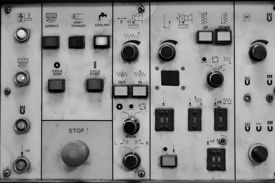
- The structure and configuration of a pneumatic industrial manipulator are selected for its operating conditions. Safety assessment covers lifting, pneumatics, mechanical and control safety, and custom gripping. Applicable requirements must be checked separately; a single standard or certificate cannot cover every function.
- Divide the assessment according to equipment characteristics, load risks, pneumatic systems, tooling type, control logic and site conditions, then identify the relevant categories of standards for each item.
- Factory inspection focuses on rated load, travel limits, braking, pneumatic leakage, air-loss protection, prevention of unintended release and document delivery. Site acceptance additionally checks foundation anchorage, installation accuracy, the air supply and trial handling under load.
- Standards applicability identifies design and inspection requirements. Determine special-equipment regulation, compulsory certification and third-party testing for the equipment and project location, then assign responsibilities in the technical agreement.
Prepared by: AUREK Engineering Technical Documentation Center · Document category: standards applicability / factory inspection / customer acceptance documentation · Version: A (engineering reference). The listed standards categories, inspection items and decision principles are engineering references. Specific classification, inspection depth and certification needs must be determined from the equipment characteristics, load risks and local regulatory requirements, using the official standards and contractual technical agreement. The complete PDF is available for download.
00Abstract
Pneumatic industrial manipulators use compressed air as their main energy source to assist operators in handling and positioning workpieces. Typical configurations include load-balancing mechanisms, rotary and pivot joints, custom tooling or vacuum gripping systems, and load-bearing columns, cantilever arms, tracks or frames. Lifting, pneumatic transmission, mechanical motion, control and gripping each present distinct risks. Their safety requirements must be checked separately; a single standard or certificate cannot describe the safety of the entire machine.
Starting from equipment characteristics, this guide maps lifting, pneumatic, mechanical and control safety requirements to factory inspection, site installation acceptance and document delivery. Certification and third-party testing are assessed separately under their applicable conditions. Typical failure modes are organized through FMEA to help engineering, quality, procurement and operating departments define project inspection plans and responsibilities.
01Introduction
Pneumatic industrial manipulators serve automotive, appliance, machining, logistics sorting, glass and sheet-handling stations, using compressed air to assist lifting, rotation, placement and release. Project assessment should consider effort reduction, takt time and station conditions together, translating intended ergonomic improvements into inspectable configuration and operating requirements.
Loads, reach, joint counts, tooling, control logic and installation conditions vary between projects. Begin safety assessment by listing the specific risks of lifted loads, pressure energy, moving mechanisms and human interaction. Then select design, inspection and protective measures appropriate to the equipment characteristics, pneumatic circuits, tooling and site installation.
Prepared by the AUREK Engineering Resource Center, this white paper supports factory inspection and customer acceptance. Define the project inspection depth, deliverables and responsibilities in the technical agreement, and carry them into the inspection plan, site-acceptance form and document list.
02Equipment Classification and Standards Applicability
The choice of standards and inspections depends first on the equipment's structure, lifting function, drive and method of use. The following sections describe common equipment forms and use them to identify the applicability of concepts such as “lifting machinery” and “special equipment.”
2.1 Pneumatic Industrial Manipulator
A Pneumatic Industrial Manipulator typically comprises a fixed base or column, a primary arm, an auxiliary arm (or multistage arm), rotary joints, pneumatic cylinders and a balance-assist mechanism, braking or locking devices, and end-effector tooling. Compressed air generates cylinder force that offsets the weight of the workpiece and mechanism, allowing the operator to guide the workpiece in a near-weightless condition. Unlike electrically driven lifting equipment, this equipment generally uses compressed air as its primary energy source rather than a main drive motor, although solenoid valves, sensors, pushbuttons, and other electrical components may be integrated for control and protection.
2.2 Pneumatic Balancers and Assist Devices
Pneumatic balancers and simpler assist devices commonly support lighter loads or hand tools, with near-floating suspension over a defined stroke. Assess supply-pressure stability, air-loss protection and release safeguards for their actual structure and function, separately from a complete articulated manipulator.
2.3 Vacuum Lifter
A vacuum lifter combines a vacuum generator or pump, a reservoir and suction cups to handle suitable sheets, panels and enclosures. Assess vacuum generation and retention, behavior after air or power loss, and compatibility with the workpiece surface. EN 13155 addresses non-fixed load-lifting attachments; determine applicability from the attachment type and project requirements.
2.4 Jib Crane
A jib crane is a rotating-arm lifting device mounted on a floor, column or wall. It may share lifting and rotation functions with a pneumatic manipulator, while differing in drive, load range and control. Assess any lifting-machinery requirements from its lifting function, rated load and structure. Apply the same equipment-based classification process to the manipulator.
2.5 Custom End-of-Arm Tooling and Vacuum-Cup Systems
End-of-arm tooling and vacuum-cup systems are normally customized for a specific workpiece and include mechanical grippers, clamps, dedicated supports, and single or multiple vacuum-cup groups. Safety concerns include retaining gripping or vacuum force, inadvertent-release prevention, behavior after loss of air or power, and compatibility with workpiece geometry. Because the equipment is highly customized, requirements are normally based on technical documentation, internal specifications, and general lifting-attachment/tooling principles; specific acceptance criteria must be stated in the technical agreement.
2.6 Rail / Frame System
Where tracks, beams or a gantry frame extend coverage, design and acceptance must cover both the arm and its supporting system. In addition to derailment prevention and positioning brakes for track travel, verify structural stiffness, connection reliability, load capacity, deformation and installation accuracy, and assess whole-machine stability during movement.
2.7 Comparison with Industrial Robots
Industrial robots are generally electrically driven, program controlled and capable of autonomous motion; their safety assessment focuses on automatic movement and human–robot collaboration. A pneumatic industrial manipulator is generally guided by an operator and mainly provides assistance and balance, without independently deciding its trajectory. The sources of risk and control methods differ. Robot standards cannot directly cover every requirement for a pneumatic industrial manipulator; select applicable standards and inspection priorities separately.
2.8 Classification as Lifting Machinery or Special Equipment
Assess lifting function, rated load, structure, intended use and installation against the official equipment catalog and management requirements at the project location. This determines whether type testing, registration in use or periodic inspection is required. Record the classification basis for the specific machine.
2.9 Applicability of CCC / CE / Third-Party Testing
Requirements depend on the region and product configuration. CCC applies within its official catalog. Export supply may involve applicable legislation and harmonized standards associated with CE. Assess the pneumatic machine and electrical subsystems against the relevant requirements. Section 09 explains certification and testing arrangements.
2.10 Standards-Applicability Reference Matrix
The matrix organizes standards by engineering topic. Check the official scope and relevant clauses against the equipment configuration, then record design measures, inspection methods and supporting evidence for the project.
| Standard / Category (Reference Framework) | Description of Potential Scope |
|---|---|
| Machinery Safety Basics ISO 12100 | Provides a general machinery-safety and risk-assessment framework and may support inherently safe machine design and hazard identification. Applicability and the specific method are governed by the official text. |
| Pneumatic system safety ISO 4414 | Provides general safety rules for pneumatic fluid-power systems, including principles for circuit design, pressure control, loss of air, and exhaust. |
| Lifting machinery safety GB 6067 series | Provides safety rules for various types of lifting machinery. Relevant provisions may apply if the equipment is classified by its attributes as jib-type or light lifting equipment; applicability must be determined from those attributes. |
| Crane design GB/T 3811 | Addresses complete-crane structures and load calculations and may provide a reference for evaluating structural strength, stability, and load capacity. |
| Electrical Safety of Machinery IEC 60204-1 / GB 5226 series | Provides safety requirements for machine electrical equipment. Relevant general and product-specific provisions may apply where the machine includes solenoid valves, sensors, controllers, or other electrical components. |
| Safety control functions ISO 13849-1 / IEC 62061 etc. | Addresses performance requirements for safety-related control parts and methods for determining the required performance level where functions such as emergency stop, safety limiting, or two-hand control are provided. |
| Ergonomics ISO 11228 series | Addresses manual handling and operating-force evaluation, supporting assessment of operator workload and manipulator guidance force. |
| Welding and fasteners Welding, GB/T 3098 | Addresses weld quality and fastener property classes and may support inspection of structural welds, bolt selection, and loosening-prevention design. |
| Lifting Attachments / Tooling EN 13155 | Addresses functional and protective requirements for non-fixed lifting attachments, including vacuum lifting devices, and may support acceptance of custom tooling and vacuum systems. |
| Export market compliance Frameworks associated with CE | Supply to export markets may involve applicable compliance frameworks and harmonized standards. Scope and assessment method must be determined from the target market and equipment attributes. |
| Compulsory Certification Catalog CCC | Applicability is governed by the latest official catalog. A purely pneumatic machine and a subsystem containing electrical components may be treated differently; determine requirements from the equipment attributes and applicable regulations. |
| Company and Customer Acceptance Specifications | Includes acceptance items in the internal quality system, factory-inspection plan, and customer technical agreement. These are as important to equipment delivery as the standards frameworks above and must be defined in the contract. |
Table 2-1. Standards-Applicability Reference Matrix. Record applicable standards, clauses, equipment attributes and verification evidence. Certification and compliance conclusions follow the relevant assessment procedure.
03Interpretation of safety requirements related to lifting
Any equipment that supports and lifts a workpiece requires assessment of lifting-related risks, including load, structure, stability, travel limits and braking. The following guidance organizes checks around these items; detailed requirements must still follow the equipment characteristics and official texts of the relevant standards.
3.1 Rated Load and Safety Margin
Rated load is a fundamental parameter for safe use. Design must define the rated lifting capacity, allowable load at maximum reach, and their relationship, with an appropriate structural safety margin. The load range that the assist mechanism can balance must correspond to the rated load so that assist force or stability is not lost near the operating limit. The rated load and limiting conditions must be clearly marked on the nameplate and in the manual and verified by the applicable factory and on-site load tests.
3.2 Structural Strength and Stability
Follow the force path through the arm, column, base and connections when checking the structure, covering static, dynamic, eccentric and impact loads and cumulative fatigue. Fixed equipment requires checks of overturning stability and foundation anchorage. Track-mounted or framed equipment requires checks of overall stability while moving and derailment prevention. Welds and high-strength bolts are critical connections; their inspection may draw on the relevant welding and fastener standards.
3.3 Travel Limits and Overtravel Protection
Provide travel limits to prevent collision, instability, or structural damage when the mechanism exceeds its intended range. Limits may use mechanical stops, limit switches, or both and must reliably stop the drive, generate an alarm, or initiate protective action at the endpoint. Verify trigger reliability and reset behavior for every limit so the system produces a dependable safe response outside the design range.
3.4 Braking, Locking, and Fall Prevention
Braking and locking are core safety functions for preventing an unintended load descent or mechanism motion. For a Pneumatic Industrial Manipulator, assess behavior after loss of air, loss of electrical power, or interruption of operation: the mechanism should hold the load at its current position or descend slowly under control, never fall suddenly. Provide reliable braking or mechanical locking at critical degrees of freedom and validate it by loss-of-air testing. Select redundancy for fall-prevention functions according to the load-risk level.
3.5 Warning Labels and Visual Information
The nameplate should state key parameters such as model, rated load and rated air-supply pressure. Provide necessary warnings at motion areas, gripping zones and hazardous points. Factory inspection must check the completeness and accuracy of each marking and select safety colors and signs under the relevant standards.
04Interpretation of safety requirements for pneumatic systems
Compressed air provides assistance and stores energy. Abnormal exhaust, leakage and pressure fluctuations can change load retention and equipment stability. Pneumatic inspection must therefore cover supply, sealing, pressure-loss response, overpressure protection and residual-energy management, with requirements determined from the official pneumatic-system safety standards.
4.1 Air-Supply Quality and Pressure Stability
Record both pressure stability and air cleanliness during supply checks. The system must operate within its design inlet-pressure range to prevent reduced assistance from insufficient pressure and shocks from pressure fluctuations. Control moisture, oil mist and particles through filtration, oil/water separation and drying where necessary. Confirm the regulation, drainage and exhaust functions of the filter-regulator assembly during inspection.
4.2 Pneumatic-Circuit Sealing and Leakage Control
Pneumatic leakage wastes energy and can also cause gradual loss of assistance, unintended load descent, or abnormal motion. Lines, fittings, valves, and cylinder connections must seal reliably and be leak-tested at operating pressure using leak-detection fluid or an electronic detector. Use reliable sealing and loosening-prevention measures on critical connections and, where necessary, a check device at the supply connection to slow abnormal depressurization.
4.3 Loss-of-Air Protection and Depressurization Behavior
After air-supply interruption or pressure loss, cylinder locks, check valves, counterbalance valves or mechanical brakes can hold position or allow controlled slow descent. Simulate air loss to verify load retention, descent speed and the safe-seating sequence. The load must remain held or reach safe support through controlled descent.
4.4 Pressure Control and Overpressure Protection
The system must provide appropriate pressure control and overpressure protection to prevent component damage or hazardous motion caused by abnormal pressure rise. Pressure-safety, relief, and pressure-limiting devices must match the system design pressure and be functionally verified during inspection. Systems with air receivers or multi-stage vacuum also require assessment of vessel and line pressure capacity and associated safety accessories.
4.5 Exhaust and Residual Energy
Before maintenance or repair, seat the load safely or provide independent support, then isolate the air supply and release residual pressure. Provide controlled exhaust and depressurization to prevent unintended movement. Include the sequence and zero-energy check in the manual and maintenance procedures.
05Machinery safety and control safety requirements
Mechanical safety addresses motion hazards such as crushing, shearing and collision; control safety addresses safety functions implemented through control logic. Use relevant mechanical safeguarding and functional safety standards to check guarding, operation, emergency stops and electrical interfaces against their official requirements.
5.1 Mechanical Guarding of Moving Parts
Rotary joints, hinges, moving cylinder components, and tooling opening/closing zones can create crushing or shearing hazards. Design should reduce hazardous gaps through inherently safe measures wherever practicable and provide guards or barriers where hazards cannot be eliminated. In areas of close operator interaction, assess the need for additional presence-sensing protection or safety-distance requirements based on the task.
5.2 Operating Method and Protection Against Incorrect Operation
Operating methods must balance efficiency and safety. Critical load-release operations should require a clear indication of intent, such as two-hand control, coordinated foot-pedal action, or a confirmation step, to reduce the risk of unintended release. A single incorrect operation must not cause hazardous motion; validate the logic through inadvertent-release-prevention testing.
5.3 Emergency Stop and Safety Functions
Where electrical controls are provided, emergency stop, safety limits, interlocks, and other safety functions must match the risk level. Functional-safety standards may guide the required reliability and architecture of safety-related control parts. Emergency stops must be readily accessible, easy to actuate, and place the equipment in a safe state; inspection must verify prompt and reliable response.
5.4 Electrical Safety (Where Electrical Components Are Included)
For equipment incorporating solenoid valves, sensors, controllers, or displays, apply relevant electrical-safety standards for machinery. Address component selection, wiring reliability, protective bonding and insulation, overload and short-circuit protection, and cable retention and protection. Interfaces between electrical and pneumatic subsystems, such as a solenoid valve controlling an air circuit, must not produce hazardous coupled motion under abnormal conditions.
5.5 Ergonomics and Operating Load
Ergonomic assessment should record guiding force, handle layout, visibility and working posture, and assess operating load against applicable ergonomics standards. Use the results to identify fatigue, unsuitable postures and resulting operating-error risks. Subjective comfort alone cannot replace a safety inspection.
06Factory Inspection Plan
The factory inspection plan should cover structures and welds, fastening and loosening prevention, pneumatic leakage and pressure, loads and travel limits, brakes and air-loss protection, tooling retention and prevention of unintended release, and document delivery. The table below helps organize inspection items. Specify methods, inspection depth and acceptance criteria in the contract or technical agreement according to the equipment characteristics; sound appearance or normal motion alone is insufficient.
| No. | Inspection Item | Description and Method (Reference) |
|---|---|---|
| 1 | Appearance inspection | Inspect coating, markings and weld appearance for visible deformation, cracks, corrosion and burrs. Verify complete, legible nameplate information and safety warnings. |
| 2 | Dimensional and assembly inspection | Check critical dimensions and mounting positions against the drawings. Verify joint clearance, bearing assembly and fits, with free movement and no abnormal binding. |
| 3 | Weld and structural parts inspection | Visually inspect welds for defects. Apply specified nondestructive testing to critical welds and structural parts, and verify that connections meet the design requirements. |
| 4 | Bolt tightening inspection | Verify fastener tightening against the design requirements, especially at main structural and joint connections. Check that specified locking provisions are correctly installed. |
| 5 | Pneumatic Leak Test | Pressurize the system to operating pressure. Use leak-detection fluid or an electronic detector to inspect lines, fittings, valves, and cylinder connections. Confirm reliable sealing and any required check-valve provisions. |
| 6 | Air-Supply Pressure Check | Verify that rated supply pressure stably reaches the design value and calibrate the pressure indication. Check air quality (water, oil, and particles) and the adjustment and drainage functions of filter-regulator components. |
| 7 | Filtration, Regulation, and Safety Components | Confirm correct installation and responsive operation of filtration, regulation, and oil-mist treatment components; functionally verify pressure-safety, pressure-limiting, and related protective devices. |
| 8 | No-load running test | Move each degree of freedom through its full unloaded stroke. Check smooth motion and brake operation, with no abnormal vibration, judder or noise. |
| 9 | Rated-Load Test | Lift, rotate and perform specified motions at rated load. Verify load balance and smooth operation, with no abrupt lifting motion or travel beyond safety limits. |
| 10 | Static-/Dynamic-Load Verification Approach | Static: Hold the test load and check structural and brake stability. Dynamic: Repeat loaded motions and check for unintended displacement or loosening. State load, duration and cycle count in the inspection plan. |
| 11 | Rotary joint and brake testing | Check smooth rotary motion and the available range. Verify that the lock or brake prevents unintended free rotation after air loss. |
| 12 | End-Stop and Anti-Collision Test | Verify timely and reliable end-stop actuation when the manipulator reaches a travel limit. Confirm that the system enters a reliably safe condition if the design range is exceeded. |
| 13 | Loss-of-Air Protection Test | Interrupt the air supply and verify that the mechanism holds position or descends slowly under control while continuously retaining the load. Confirm protection against a sudden gravity-driven drop. |
| 14 | Tooling Grip / Vacuum-Holding Test | Functionally test the tooling or suction cups. Verify stable gripping of representative workpieces or vacuum holding at rated load, and check correct operation of directional and control components. |
| 15 | Inadvertent-Release Prevention Test | Verify that safeguards permit release only under safe conditions. Test release inhibition after air or electrical-power loss. |
| 16 | Vacuum-Retention Test | For equipment with a vacuum system, test vacuum retention after loss of air/power. Confirm that the vacuum level remains within the allowable range for the specified time and inspect vacuum-generation and control components for leakage. |
| 17 | Noise, Smoothness, and Operating Force | Confirm that operating noise is acceptable and motion is smooth and free of binding. For hand-guided equipment, verify that operating force is within a reasonable ergonomic range. |
| 18 | Nameplate, Labels, and Manual Check | Check complete and correct nameplate data and warnings. Verify that the manual includes safety, operating and maintenance procedures, with applicable pneumatic/electrical diagrams and inspection records. |
Table 6-1. Factory Inspection Plan. Select items for the configuration and state methods and criteria. Record each result, obtain the responsible signatory and archive it against the machine number.
07On-Site Installation and Acceptance
After installation, verify the effects of the foundation, installation accuracy, air supply and working environment on whole-machine safety. Passing factory inspection does not replace site acceptance. Use the table below to prepare the site acceptance form and document every result in a written acceptance record.
| No. | Acceptance Item | Description and Method (Reference) |
|---|---|---|
| 1 | Foundation and Anchoring | Compare the foundation drawing with the installed foundation and confirm that site conditions meet the design requirements. Check anchor-bolt specifications, embedded locations, tightening, and loosening prevention, and verify the reliability of base-to-foundation connections. |
| 2 | Installation Verticality and Levelness | Measure the verticality and levelness of columns, jibs, and other components using a level or plumb reference. Confirm that there is no material inclination and correct with shims where necessary. |
| 3 | Working-Radius Verification | Confirm that the installed working radius meets design and use requirements and that the motion zone is unobstructed. At maximum reach, verify that joints do not interfere and that required safety clearance remains. |
| 4 | Lift-Stroke Verification | Operate to the travel limit both unloaded and at rated load. Verify the accuracy and stopping reliability of limit switches or mechanical stops, and recalibrate limits if overtravel occurs. |
| 5 | On-Site Air-Supply Pressure | Measure site supply pressure and confirm that it remains within the specified inlet range. Check supply-line diameter and filtration, and verify stable pressure with controlled pulsation. |
| 6 | On-Site Air Quality | Check moisture, oil, and particle levels in the compressed air and verify correct operation of filtration, water separation, and drying equipment. Where necessary, compare pressure indications with sensor readings. |
| 7 | Operating Space and Interference | Have the operator simulate normal work and check the entire motion envelope for interference with the ceiling, adjacent equipment, workpieces, or personnel routes. Confirm that the operating space meets ergonomic requirements. |
| 8 | Rated-Load Trial Handling | Under appropriate safety supervision, handle the rated load or an equivalent test load through lifting, transverse movement, and other required motions. Verify balance and responsiveness under actual operating conditions, with particular attention to brake response under load. |
| 9 | Workpiece-Gripping Verification | Trial-handle an actual workpiece to verify the compatibility and reliability of the tooling or suction cups. For vacuum lifting equipment, check sealing and vacuum level. Confirm correct release and reset behavior. |
| 10 | Operator Training | Train operators in machine functions, safe operation, and emergency response. Confirm familiarity with brakes, limits, emergency stops, and other safety devices, then document training completion. |
| 11 | Inspection-Checklist Delivery and Acknowledgment | Provide the user with daily inspection and maintenance checklists stating frequencies, items, and criteria. Obtain acknowledgment of receipt and understanding of the implementation responsibility. |
Table 7-1. On-Site Installation and Acceptance Plan (Reference). On-site acceptance must produce a written report stating conclusions and corrective-action recommendations. Issues must be corrected and pass reinspection before the equipment is released for use.
Site acceptance should focus on vibration and positioning errors caused by inadequate foundation stiffness, unstable assistance or component wear caused by an unsuitable air supply, and collision risks from insufficient space. The contract or technical agreement should assign responsibility for providing and verifying site conditions.
08Document delivery list
Accompanying documentation records the equipment's technical condition and supports traceability for operation, maintenance and acceptance. Recommended documents include a certificate of conformity, instructions, pneumatic and electrical diagrams, inspection records, inspection checklists and a site acceptance form. Specify the delivery scope according to the equipment configuration and contract or technical agreement.
| Document Name | Purpose and Contents (Reference) |
|---|---|
| Certificate of Conformity | States the product name, model, serial number, manufacturer, and manufacture date and serves as evidence that the product passed factory inspection. |
| Operation Manual | Describes machine structure and operating principles, operating steps, safety precautions, maintenance, and common troubleshooting. Pneumatic and electrical schematics and a parts list should be included. |
| Packing List | Lists the components, spare parts, and tools shipped with the equipment for verification at delivery and receipt. |
| Factory Inspection Record / Report | Summarizes the result and disposition of each factory-inspection item, including records for key items such as pressure, load, limits, loss-of-air protection, and tooling. |
| Pneumatic and Electrical Schematics | Provides pneumatic and electrical control schematics for on-site connection, maintenance, and troubleshooting. |
| Risk-Assessment Record | Documents identified equipment hazards and analysis of the corresponding safeguards as supporting evidence for safety design and acceptance. |
| Wear-Parts List | Lists consumable and wear parts, including seals, filter elements, and brake components, together with recommended replacement intervals for maintenance and spare-parts planning. |
| Inspection and Maintenance Plan | Provides a daily inspection checklist and maintenance manual stating inspection items, frequencies, and criteria to support long-term safe operation. |
| Tooling / Vacuum-Holding Test Record | For custom tooling or suction-cup systems, provides performance-test records for gripping force or vacuum holding, vacuum retention, and related functions. |
| On-Site Acceptance Form | Signed by the user or a third party after the on-site inspection passes, confirming that installation and functions meet the agreed requirements. |
| Training Records | Attendance or acknowledgment records for required operator safety and operating training. |
Table 8-1. Document Delivery List (Reference). The contract or technical agreement must define the required document scope and format, and the agreed terms govern.
09Safety Certification and Third-Party Testing
Organize certification and testing according to equipment attributes, load risk and local requirements. Certification and compliance conclusions follow the relevant assessment procedure. Record requirements, evidence, responsible parties and milestones for the specific machine.
9.1 Determination as Special Equipment / Lifting Machinery
Whether the equipment is regulated as lifting machinery or special equipment—and may therefore require type testing, registration for use, or periodic inspection—must be determined from its lifting function, rated load, structure, and installation method against the catalogs and management rules at the project location. The conclusion may vary with load range, local regulatory interpretation, and operating conditions. Official regulations and catalogs take precedence.
9.2 Compulsory Product Certification (e.g., CCC)
Compulsory product certification normally applies to products or electrical components within a specified catalog. Applicability may differ between a purely pneumatic machine and a subsystem containing electrical components. If motors, controllers, or other electrical components are integrated, determine their certification requirements from the latest official catalog and equipment attributes. The contract should state whether an application is required and which party is responsible.
9.3 Export-Market Compliance (e.g., Frameworks Associated with CE)
Supply to export markets may involve applicable compliance frameworks and harmonized standards. Determine scope, assessment method, and technical-documentation requirements from the target-market rules and equipment attributes. Such compliance normally involves risk assessment and preparation of technical documentation and differs from third-party certification; a qualified professional must confirm the project-specific requirements.
9.4 Third-Party Testing and Witnessing
Where the customer or industry requires third-party involvement, a qualified organization should perform the relevant type tests or witness factory inspection or site acceptance. Before implementation, specify the contractual inspection scope, acceptance criteria, required documents, organization, costs and division of responsibilities.
10FMEA risk analysis
FMEA links each failure mode to its causes, consequences and control measures. The table below organizes typical pneumatic industrial manipulator risks for design, inspection and acceptance. These are general examples; design and safety engineers must complete the analysis and risk ratings for the specific project equipment.
| Risk / Hazard | Possible Causes | Potential Consequences | Mitigation Measures (Reference) |
|---|---|---|---|
| Unexpected Load Release | Pneumatic pressure loss; balance-assist failure; overload | Workpiece drop causing personal injury or equipment damage | Provide reliable braking/locking and check valves; limit descent speed; clearly establish the rated load and strictly prohibit overload. |
| Crushing / Shearing Injury | Personnel in the motion path; insufficient joint clearance | Body pinched by moving components or tooling | Reduce hazardous gaps or provide physical guarding; establish safe-work procedures; use two-hand or confirmation-based control for critical release actions. |
| Structural Failure / Fracture | Accumulated fatigue; weld defects; unsuitable material selection or insufficient design margin | Failure of an arm or connection, potentially causing a serious accident | Verify the structure against loads and safety margins; inspect welds to applicable specifications; schedule periodic structural and fatigue inspections; use conforming materials. |
| Air-Supply Leakage / Pressure Loss | Aged lines; loose fittings; valve failure | Assist force gradually fails or motion becomes abnormal, causing the workpiece to descend | Periodically inspect and replace seals and tighten fittings; provide pressure monitoring and alarms; use loss-of-air protection to hold the load or permit controlled slow descent. |
| Loss of Vacuum | Poor suction-cup sealing; vacuum-component failure | Vacuum-held load falls | Select suitable suction cups and seals; provide vacuum retention and indication; regularly clean and replace aged components; provide a low-vacuum alarm and holding logic. |
| Electrical-Control Failure (If Present) | Solenoid-valve failure; loose wiring; missing protection | Loss of function or safety function | Apply relevant electrical-design standards; provide required protection and emergency stop; secure wiring reliably; schedule periodic electrical inspections. |
| Overload / Incorrect Operation | Use above the rated load; operator error | Structural damage or unintended motion | Clearly mark load limits and train operators; provide error-prevention and confirmation logic; add load sensing or limiting measures where necessary. |
| Noise Hazard | High-velocity airflow; mechanical friction | Hearing effects from prolonged exposure | Optimize pneumatic circuits to reduce turbulent-flow noise; apply noise controls at critical locations; provide required hearing protection in the work area. |
Table 10-1. Typical Failure Mode and Effects Analysis (Example). This table identifies principal risks and control directions. For an actual project, design and safety engineers must complete the FMEA and risk rating using equipment-specific details.
11Conclusion
Assess pneumatic industrial manipulator safety separately for equipment characteristics, loads, pneumatic systems, tooling, control logic and site conditions. A single standard or certificate cannot replace checks of all whole-machine safety requirements. Each risk must correspond to defined design measures, inspection methods and protective requirements.
At the factory, focus on rated load, travel limits, braking, pneumatic leakage, air-loss protection, prevention of unintended release, tooling retention and document delivery. At the site, additionally check foundation anchorage, installation accuracy, air supply, working space and trial handling under load. Keep separate records for both stages, and release the equipment for use only after site issues have been corrected and rechecked.
Delivered documents should match the equipment configuration and technical condition, including applicable certificates of conformity, instructions, pneumatic and electrical diagrams, inspection records, checklists and site acceptance forms. Standards applicability is a design and inspection reference and does not automatically establish compliance. Special-equipment regulation, compulsory certification and third-party testing requirements must still be determined from equipment characteristics and local rules, with responsibilities assigned in the contract or technical agreement.
At the start of the project, define equipment classification, inspection depth, certification needs and document scope in the contract and technical agreement. Use these requirements to create records throughout design, manufacture, factory inspection, site acceptance, operation and maintenance, supporting technical traceability, change management and accountability.