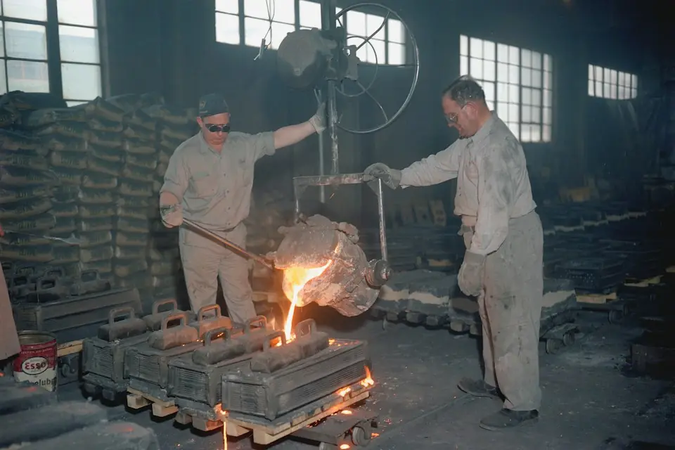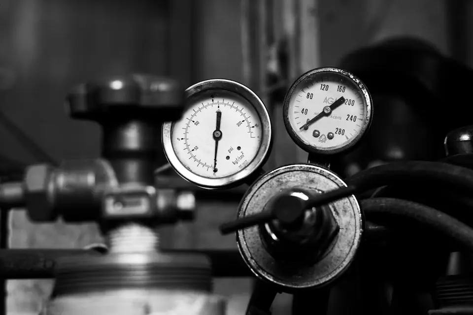
- No unintended release on air loss; controlled release afterward is the release principle for industrial handling tooling. Retain the load during a fault, then release at low speed with diagnostic and reset capability once interlocks permit. Loss of air must not itself be treated as an opening command.
- Loss-of-air protection requires coordinated mechanical self-locking, geometric support, pressure retention, leak detection, pressure-decay monitoring, release interlocks, operating procedures and maintenance reset. An air receiver or pressure switch provides only part of this protection.
- Check gripping force using the equivalent-load method, including acceleration, emergency-stop impact, minimum friction and jaw wear. For the stated 300 kg hot-workpiece example, target total normal force is at least approximately 36.7 kN.
- Use multiple signals for air-loss diagnosis: P1/P2/P3 pressure, pressure-decay rate, jaw displacement, lock engagement and support confirmation. The recommended total air-loss locking response is ≤150 ms.
Organization: Jiangsu AUREK Intelligent Technology Co., Ltd. (AUREK Intelligent Technology Research Group, Lianyungang, Jiangsu) · Validation period: 2023.05—2026.04 · Document type: industrial engineering methods. Parameters are identified as calculated, test-record or engineering-recommended values and must be reviewed for each project. This document is not a third-party certification, type-test report, customer acceptance record or quality certificate. The full PDF is available for download.
00Abstract
Pneumatic industrial manipulators, pneumatic handling systems, robot end effectors, vacuum lifters and special-purpose loading tooling require assessment of load retention after sudden pressure loss, hose rupture, valve faults and control-signal failure. Declining grip or unintended release can cause falling workpieces, equipment collisions, burns and production stoppages. This study organizes methods for loss-of-air protection, safe release and engineering validation around these risks.
No unintended release on air loss; controlled release afterward means prioritizing grip retention, stopping handling and prohibiting suspended release when air is lost. Low-speed release with diagnostic and reset capability is permitted only when the workpiece is supported, the tooling is in a safe position, the manipulator or robot is in an authorized release pose, personnel are in a safe area and control interlocks are satisfied.
The following sections cover gripping-force checks, self-locking, geometric support, pressure retention and leak monitoring, release interlocks, maintenance reset and validation for pneumatic clamping, jaw, vacuum, internal-expansion, hook, turnover and hot-workpiece tooling. Pressure, time, grip force, slip and response-time values are engineering references or compiled internal test values and must be checked against the workpiece, tooling structure, air supply, motion profile and site safety requirements.
01Introduction
Handling tooling is fitted to pneumatic industrial manipulators, pneumatic balancers, gantry manipulators, industrial robots, jib cranes and special-purpose loading systems to grip, support, orient, transfer and release workpieces. Design must cover rated conditions and foreseeable faults such as air-supply failure, control faults, jaw wear, eccentric loading, radiant heat and maintenance errors, limiting escalation of risk after failure.
Air pressure commonly generates grip, drives jaws and actuates release. Where holding depends entirely on continuous supply, supply interruption, hose rupture, disconnected couplings, sticking spools, unintended release-valve actuation or clamp-chamber leakage can rapidly reduce grip and cause slipping, falling or impact. Hot castings, forgings and heat-treated parts also involve scale, variable friction and limited access for personnel intervention; these conditions must be included in the protection design.
02Research objects and boundary conditions
2.1 Research objects
The study covers pneumatic wraparound clamps, jaw grippers, vacuum tooling, internal-expansion grippers, hooks, turnover tooling and hot-workpiece handling tooling, as well as other custom industrial tooling. It focuses on safe release, air-loss protection and engineering validation for pneumatic industrial manipulators, pneumatic balancers, gantry manipulators, robot end effectors, special-purpose loading systems, jib cranes and vacuum lifters.
2.2 Boundary conditions
This method addresses pneumatic and combined tooling under air loss, leakage, unintended release and maintenance reset. Each project must still complete risk assessment, mechanical strength calculations, control-system safety validation, site commissioning and customer acceptance. Design inputs must specify workpiece mass, dimensions, surface, temperature, center of gravity, gripping method, motion profile, cycle time, personnel working methods and supply conditions, followed by project-specific design, checks and validation.
03Loss-of-air risks and typical failure modes
Failure analysis should include workpiece weight, acceleration, emergency-stop impact, orientation changes, jaw wear, reduced friction, radiant heat, center-of-gravity shifts and operator error. Although wraparound, jaw, internal-expansion, vacuum, hook and turnover tooling have different mechanisms, all require assessment of reduced retention, unintended release, unintended motion and inability to reset safely.
| No. | failure mode | Description of main risks |
|---|---|---|
| 1 | The main compressed-air supply is suddenly interrupted | When the pressure supply to the clamping cylinder disappears, without mechanical locking or pressure-maintaining measures, the clamping force may decline rapidly. |
| 2 | Main compressed-air supply pressure drops slowly | Grip decreases gradually; without low-pressure warning, handling may continue with insufficient force. |
| 3 | Air-hose rupture | The branch pressure drops rapidly, which may cause the clamping chamber to lose pressure or the actuator to malfunction. |
| 4 | quick connector disconnect | It often manifests as instantaneous leakage and needs to be identified through the pressure drop rate and pressure threshold. |
| 5 | Sticking Valve Spool | May cause incomplete gripping, incomplete release or unintended exhaust. |
| 6 | Release valve malfunction | If the release interlock is insufficient, unintended release may occur when the workpiece is suspended. |
| 7 | Clamping chamber leakage | The clamping force decays slowly, possibly causing the workpiece to slip. |
| 8 | Air Receiver or Check-Valve Failure | The local pressure holding capacity is reduced and the air loss holding time is shortened. |
| 9 | Incorrect Pressure-Sensor Signal | The control system may misjudge the clamping or air loss status. |
| 10 | gripper-jaw wear | The contact area, friction coefficient and geometric limiting capability are reduced. |
| 11 | High temperature damages air line, seals, and sensors | It may cause air leakage, signal drift, or abnormal operation. |
| 12 | Operator mistakenly presses release button | Without dual confirmation and a support interlock, the load could be released inadvertently while suspended. |
| 13 | Unintended Start During Maintenance | When maintenance personnel are in a dangerous area, malfunction of the clamp may cause injury. |
| 14 | Workpiece released inadvertently before it is securely seated | The workpiece may fall directly and is the key prevention and control target of the release interlock. |
| 15 | Center of gravity shift causes eccentric load slip | Eccentric loads increase the force on one side of the gripper, which may induce rotation, overturning or slipping. |
Table 1. Air-Loss Risks and Typical Failure Modes
Design reviews should address mechanical self-locking, geometric support, pressure retention, leak detection, pressure-decay monitoring, release interlocks, operating procedures and maintenance reset individually, checking each function after air loss. Adding only an air receiver or pressure switch does not provide complete protection.
04Design principles for safe release and loss-of-air protection
Coordinate risk assessment, inherently safe geometry, mechanical redundancy, pressure retention, monitoring, interlocks, controlled release, maintenance reset and testing. Retain the load after a fault. Permit low-speed release only after support, personnel safety, position and all control conditions are confirmed.
Intrinsic safety should minimize dependence on pneumatic holding alone through V-grooves, contoured supports, under-supports, side stops, limit stops, and heat-resistant jaws; mechanical redundancy should combine wedge self-locking, spring-loaded locking pins, pawl mechanisms, geometric supports, and limit stops to provide passive retention after loss of air; control interlocks should permit release only after workpiece-support confirmation, tooling-position confirmation, manipulator or robot pose confirmation, personnel-safety-zone confirmation, pressure-status confirmation, and sensor-signal consistency confirmation.
| Comparison | standard pneumatic tooling | Tooling with Air-Loss Protection |
|---|---|---|
| Clamping and holding method | It mainly relies on the continuous supply of pressure by the cylinder. | Combined pressure retention, mechanical locking, geometric support, monitoring and release interlocks |
| Air-supply shutoff response | The clamping force may decrease as the pressure decreases. | Stop handling, lock mechanically, retain the grip and inhibit suspended release |
| Release conditions | Often triggered by a single button or ordinary valve control. | Interlock conditions shall include workpiece-seated confirmation, position confirmation, pose confirmation, personnel safety, and pressure status. |
| Leak detection method | Rely more on pressure gauges or manual observation. | P1, P2, P3 pressure monitoring, pressure drop rate judgment and signal consistency diagnosis. |
| maintenance safety | Maintenance status may depend on operating procedures. | Controlled depressurization, manual reset, maintenance confirmation and restart inhibition |
| Suitable Applications | Suitable for low-risk, light-load, and stable compressed-air supply scenarios. | Suitable for high temperature, heavy load, suspended handling, posture changes and non-standard handling scenarios. |
| Dependence on personnel/compressed-air supply | higher. | Reduced dependence on supply continuity through pressure retention and mechanical holding, with release interlocks |
Table 2. Pneumatic Tooling and Tooling with Air-Loss Protection
05Clamping force calculation method and representative engineering verification calculation
5.1 Basic logic of calculation
Friction-based tooling should use an equivalent-load method rather than estimating from static weight alone. Inputs include weight, handling acceleration, emergency-stop impact, orientation changes, minimum friction coefficient, high-temperature scale, jaw wear and eccentric loading:
Fe is equivalent load (N), including motion and impact. m is workpiece mass (kg), g = 9.81 m/s², a is maximum handling acceleration (m/s²), and φ is the emergency-stop impact factor, selected from the motion profile and braking behavior. The target total normal force is:
Ntotal is target total normal force (N), Ks the safety factor and μmin the minimum friction coefficient considering heat, scale, oil, wear and surface variation. Effective cylinder output is:
where Fc is the effective output force of the cylinder (N); P is the working pressure (Pa); A is the effective area of the piston (m²); η is the transmission efficiency; Fr are sealing resistance, spring resistance and mechanism friction resistance (N). If the clamping force is amplified by force-increasing mechanisms such as wedges, toggle levers, and eccentric mechanisms, the transmission ratio, efficiency, wear, jamming, thermal expansion, release resistance, pin shear, elastic deformation of the clamping jaw, and load-bearing capacity under air loss locking conditions should also be checked.
5.2 Representative Calculation and Validation Inputs
The following inputs are associated with the AUREK engineering-validation records for 2023.05–2026.04. They apply to the stated calculation and test conditions. Review project use against raw records, design documents and site safety requirements.
| Project | Recorded Test Input |
|---|---|
| Workpiece type | High temperature iron castings or forgings |
| Workpiece Mass | 300 kg |
| Overall reference dimensions | 900 mm × 450 mm × 250 mm |
| Workpiece surface temperature/ambient temperature | 250 °C / 25 °C |
| Workpiece center of gravity offset | ≤80 mm |
| Maximum acceleration of handling | 0.3 g |
| Emergency stop impact correction coefficient φ | 1.2 |
| Minimum friction coefficient μ under high temperature oxide scale conditionsmin | 0.25 |
| Clamping force safety factor Ks | ≥2.0 |
Table 3. Representative Hot-Workpiece and Heavy-Load Test Inputs (2023.05–2026.04)
Substitute into equation (1) and equation (2):
For this example, total normal force is at least 36.7 kN. With two jaws, the calculated target is about 18.4 kN per jaw. A target of 20–22 kN per jaw accommodates the stated wear, pressure, thermal, eccentricity and assembly considerations. Combine friction gripping with V-grooves, support steps, contoured or bottom supports where appropriate.
06Mechanical self-locking and safety release mechanism design
Mechanical self-locking provides passive protection after loss of air, retaining the load when supply or control signals fail and preventing immediate jaw opening as pressure decays. State detection, interlocks and release sequencing remain control-system functions; neither replaces the other. For hot, heavy or suspended loads, consider mechanical redundancy combining self-locking wedges, spring locking pins, pawls, geometric supports and stops.
Use two stages: unlock the mechanical restraint, then open the jaws under control. Unlock only after workpiece support, tooling position, manipulator/robot pose, personnel safety, pressure and diagnostic lock status are confirmed. Use throttled exhaust, proportional control or mechanical speed limiting for slow opening. Emergency manual release also requires load support and a guard, double action, dedicated key or mechanical confirmation to prevent accidental operation.
| Parameter items | Engineering reference values/recommended verification indicators | design description |
|---|---|---|
| wedge angle | 5°~7° | Taking both self-locking ability and release resistance into consideration, the state of the friction surface needs to be considered. |
| Lock pin entry time | ≤100 ms | Used for rapid mechanical locking after loss of air or power. |
| Total response time of air loss lock | ≤150 ms | Verification target from fault recognition to completed locking |
| Normal controlled release time | 0.8~1.5 s | Avoid impact or bounce caused by instant release. |
| Normal release and claw opening speed | ≤80 mm/s | Used to reduce impact during controlled release after workpiece seating is confirmed. |
| Emergency manual release claw opening speed | ≤50 mm/s | Manual release should be slow, abortable and confirmable. |
| Maximum elastic deformation of the jaw end | ≤0.2 mm | It needs to be checked based on the length, material and stress state of the clamping jaw. |
| Lock pin shear safety factor | ≥3.0 | Checks critical load capacity while held after air loss |
| Safety factor of wedge contact surface | ≥1.5 | Contact stress, wear and lubrication conditions need to be considered. |
| Maximum equivalent stress of main load-bearing parts | ≤60% of the allowable stress of the material | As a reference boundary for structural strength design. |
Table 4 Mechanical structure engineering reference indicators
For hot-workpiece tooling, also assess insulation pads, heat-resistant jaws, metal hoses, radiation-protected wiring and sensor shielding. Place hoses, seals and sensors on the side with less radiant exposure where possible, using metal hoses, insulating sleeves or heat shields to reduce thermal damage.
07Pneumatic Pressure Retention and Leak Detection
Organize pneumatic design around supply filtration, local pressure retention, fault isolation, pressure monitoring, controlled exhaust and maintenance depressurization. Typical components include filter-regulators, check valves, pressure-retention valves, air receivers, safety shutoff valves, throttled exhaust valves and safety exhaust valves. Monitoring covers main pressure sensor P1, branch pressure sensor P2 and clamp-chamber pressure sensor P3, together with pressure-drop rate, leak classification and hose protection in hot areas.
| Parameter items | Engineering Reference / Test-Record Value | Description |
|---|---|---|
| Rated air supply pressure | 0.5~0.8 MPa | It is suitable for common industrial compressed air conditions and needs to be calibrated according to the on-site compressed-air supply. |
| Test initial air supply pressure | 0.60 MPa | Initial condition for the stated tests |
| Low-Pressure Warning Threshold | P1 < 0.45 MPa, lasting ≥200 ms | Recognizes insufficient air supply and inhibits the start of a new cycle. |
| Loss-of-air protection trigger pressure | P1 < 0.35 MPa or P2 < 0.35 MPa | Triggers stop of handling, mechanical locking and prohibition of release. |
| Rapid leak trigger conditions | Pressure drop rate ≥0.08 MPa/s | Identify sudden leaks such as air-line rupture and disconnected joints. |
| Pre-clamping pressure | 0.18 MPa (approximately 30% of rating) | For use in soft contact stages. |
| Normal clamping pressure | 0.60 MPa | Used to simulate normal clamping conditions. |
| Permitted Pressure Variation | ±5% (approximately ±0.03 MPa) | Suggested verification indicators for pressure stability. |
| Pressure sampling period/recording frequency | ≤20 ms / ≥50 Hz | For pressure decay and rapid leak identification. |
| Main compressed-air supply - branch abnormality judgment | |P1−P2| > 0.08 MPa, lasting ≥300 ms | Identify abnormalities in the main compressed-air supply and branch air paths. |
| Clamping cavity abnormality judgment | |P2−P3| > 0.10 MPa, lasting ≥300 ms | Identify clamping chamber leaks or valve block abnormalities. |
Table 5: Pneumatic-System Engineering Reference Values and Compiled Internal Test Values
The pressure decay rate is determined by the following formula:
Rp is pressure-decay rate (MPa/s), ΔP the pressure change and Δt the sampling interval. The stated test threshold, 0.08 MPa/s, triggers rapid-leak protection. Set slow-leak alarm levels for circuit volume, sealing and required holding time. Persistent abnormal P1/P2/P3 differences indicate sensor, valve or circuit faults and require a conservative safe response.
08Control logic and release interlock conditions
Release requires workpiece support, tooling position, manipulator/robot pose, grip status, lock status, personnel safety, a release command, pressure status and consistent sensor signals. Before support is confirmed, reject release. Conflicting signals require a conservative safe state: stop handling, retain the grip and inhibit release.
| response level | Trigger condition | System response |
|---|---|---|
| First-level warning | P1 < 0.45 MPa, lasting ≥200 ms | Low-pressure warning; inhibit new cycles |
| Secondary protection | P1 < 0.35 MPa or P2 < 0.35 MPa | Stop handling, engage mechanical locking and inhibit release |
| Level 3 Emergency Stop | Pressure drop rate ≥0.08 MPa/s, or abnormal gripper jaw displacement | Stop immediately, engage the locking pin, maintain the grip, and inhibit release while suspended. |
| reset condition | Pressure restored, leakage eliminated, workpiece securely seated, manual confirmation complete, lock reset, sensor signals consistent, and work area safe | Allows access to controlled release, re-clamping or manual handling processes. |
Table 6. Air-Loss Response Logic
Apply the principle retain the load after a fault; release only when confirmed. Supply interruption must not act as a release command, including for hot or heavy workpieces.
09Risk Analysis and FMEA
FMEA identifies critical failures, prioritizes risks and links them to corrective measures. This study uses severity S, occurrence O, detection D and risk priority number RPN, with RPN = S × O × D. Scores in the table are examples from an internal engineering assessment model; project comparisons and risk rankings require reassessment.
| failure mode | S | O | D | Initial RPN | Improvement measures | After improvement |
|---|---|---|---|---|---|---|
| The main compressed-air supply is suddenly interrupted | 5 | 4 | 4 | 80 | Check valve, pressure-holding valve, mechanical locking and air-loss release inhibition | 20 |
| The main compressed-air supply slowly decreases | 4 | 3 | 4 | 48 | Low pressure warning, prohibition of new cycles, pressure trend monitoring | 16 |
| Air-hose rupture | 5 | 3 | 4 | 60 | Pressure-decay detection, metal hose, hose restraints and mechanical locking | 15 |
| quick connector disconnect | 5 | 3 | 4 | 60 | Locking coupling, P2 monitoring and coupling-retention measures | 15 |
| Release valve malfunction | 5 | 3 | 4 | 60 | Support interlocking, double confirmation release, safety output monitoring | 12 |
| gripper-jaw wear | 4 | 4 | 3 | 48 | Replaceable wear-resistant blocks, wear scales, and regular inspections | 18 |
| The lock pin is not in place | 5 | 3 | 3 | 45 | Dual position detection, protected locking pin and handling inhibition on failure | 15 |
| Incorrect Pressure-Sensor Signal | 4 | 3 | 4 | 48 | P1/P2/P3 cross-check, periodic calibration | 16 |
| Radiant-Heat Damage to Hoses | 5 | 3 | 3 | 45 | Metal hose, insulation jacket, temperature recording | 15 |
| Accidental Manual Release | 5 | 3 | 4 | 60 | Protective cover, double action, special key, support confirmation | 12 |
| Unintended Start During Maintenance | 5 | 3 | 3 | 45 | Maintenance mode, lockout and tagout, manual reset confirmation | 15 |
| Release command received while the workpiece is unsupported | 5 | 3 | 4 | 60 | Support sensor, position interlock, release command rejection | 10 |
| Clamping chamber leakage | 4 | 4 | 3 | 48 | P3 monitoring, pressure drop rate judgment, leakage classification alarm | 16 |
| Air Receiver or Check-Valve Failure | 4 | 3 | 4 | 48 | Pressure-retention test, periodic check-valve inspection and air-loss holding test | 16 |
Table 7: Example of FMEA for air loss protection of industrial handling fixtures (RPN is an internal assessment model of the enterprise and is not used as a third-party certification conclusion)
In this assessment model, S=5 represents potential serious injury, major equipment damage or a dropped hot workpiece. RPN ≥50 requires corrective action and retesting or a dedicated review; 30 ≤ RPN <50 requires project review, assigned responsibility and residual-risk assessment; RPN <30 remains subject to inspection and record retention.
10Test verification plan
Before delivery, complete design validation, parameter adjustment and risk review using the table below. Retain raw test records and calibration information to support the corresponding conclusions.
| test items | Test purpose | Acceptance concerns |
|---|---|---|
| Rated clamping test | Verify clamping capacity under rated working conditions | There is no abnormal slippage and the deformation of the clamping jaw is within the allowable range. |
| Dynamic handling test | Verify holding ability under acceleration and emergency stop impact | The workpiece has no obvious slippage and the locking state is stable. |
| loss-of-air test | Verify main air supply interruption protection logic | Stop handling, lock mechanically and inhibit release |
| slow leak test | Verify low pressure warning and leak identification | It can alarm in different levels and prohibit new cycles. |
| Quick leak test | Verify response to air-hose rupture or connector disengagement | Trigger the designed emergency response, retain the grip and inhibit suspended release |
| Support interlock test | Verify rejection of release before workpiece seating is confirmed | The system refuses to release. |
| controlled release test | Verify low-speed release after workpiece seating is confirmed | Release is smooth, with no significant impact or bounce. |
| High temperature radiation test | Verify component status in high temperature environments | No obvious thermal damage or abnormal alarm. |
| Life cycle test | Verify the durability of jaws, lock pins, valve blocks, and seals | There is no abnormal wear or functional failure of key components. |
| Maintenance reset test | Verify manual confirmation and reset process after failure | Inhibit automatic cycles before reset; verify consistent states afterward |
Table 8: Enterprise recommended verification plan (recommended to record P1/P2/P3, pressure drop rate, clamping jaw displacement, slip amount, response/release time, etc.)
11Engineering Verification Practices and Representative Records
During 2023.05—2026.04, the AUREK Intelligent Technology Research Group performed and documented engineering validation of custom pneumatic industrial manipulators, pneumatic handling systems and industrial tooling. Validation covered grip retention as supply pressure falls, protective triggering during rapid leaks or coupling disconnection, mechanical locking after air loss, controlled release and prevention of unintended suspended release, and support, position and personnel-safety interlocks. It also examined safe stopping and controlled release with air-receiver/valve combinations and the operating conditions of high-temperature components. The design and validation procedure follows:
Representative validation used a 300 kg hot workpiece and initial supply pressure of 0.60 MPa. Low pressure, air loss, rapid leakage, unintended release and controlled release were tested to check retention, mechanical-lock response and release interlocks. The table summarizes the corresponding engineering records:
| No. | Test conditions | Key settings | Recorded Results |
|---|---|---|---|
| 1 | Normal air supply clamping | P=0.60 MPa, keep for 15 minutes | 15 min slippage 0.28 mm; P3 ≈ 0.594 MPa |
| 2 | Low-Pressure Warning | P1 < 0.45 MPa, lasting ≥200 ms | P1=0.446 MPa, alarm after 236 ms |
| 3 | Main compressed-air supply decreases slowly | 0.60→0.35 MPa / 10 s | Level 2 protection entered and locking completed at 10.2 s |
| 4 | The main compressed-air supply is suddenly cut off | drops to 0 MPa within 0.5 s | Total locking response 104 ms, 5 min slip 0.62 mm |
| 5 | Rapid leakage of clamped branch circuit | P3 0.60→0.25 MPa / 3 s | Pressure-decay rate ≈0.116–0.118 MPa/s; Level 3 emergency stop |
| 6 | quick connector disconnect | P2 dropped to 0.10 MPa within 1 s | P2 reaches 0.35 MPa in about 496 ms; locking pin engaged |
| 7 | Release valve malfunction | The workpiece is suspended and the support confirmation is invalid. | Release output remains inactive; tooling retains the grip |
| 8 | Release after the workpiece is securely seated | Release time 0.8~1.5 s | Controlled claw opening 1.12 s, maximum claw opening speed 68 mm/s |
| 9 | High temperature radiation test | 250 °C heat source for 30 minutes | The surface of the air hoses is 57 °C, the sensor housing is 48 °C, and there is no abnormal alarm. |
| 10 | Maintenance reset simulation | Pressure recovery 0.60 MPa, manual confirmation | Automatic cycles inhibited before reset; states consistent afterward |
Table 9. Representative engineering-validation conditions and record summary (2023.05–2026.04)
12Engineering Application Analysis
The method can support assessment of hot-forging handling, casting cleaning and transfer, heat-treatment loading, large plates and boxes, and tooling for robots, pneumatic industrial manipulators, pneumatic balancers and vacuum handling. Automotive parts, motor stators, sheets, tires and battery compartments each require design validation for their contact conditions, center of gravity, orientation and site conditions.
Application reviews should examine retention after air loss, unintended-release interlocks, smooth controlled release and safe reset after maintenance, and assess how heat, dust, oil and supply fluctuations affect design margins.
For vacuum tooling, check vacuum retention, cup aging, surface roughness and leak monitoring. For hooks, check retention latches, center of gravity and orientation limits. For turnover tooling, check inertial loads and secondary locking. For internal-expansion tooling, check contact wear, declining expansion force and bore-size variation.
13Conclusion and outlook
Conclusions: Retain the grip after air loss. Combine mechanical self-locking, geometric support and pressure retention to address hose rupture, coupling separation, valve faults and control-signal failure. Size gripping force for dynamics, minimum friction, heat and wear. Diagnose faults through P1/P2/P3 pressure, decay rate, jaw displacement, locking and support signals. Release requires confirmed support, personnel safety and all interlocks. Validation covers air loss, leakage, dynamic handling, controlled release and maintenance reset.
Further research: Project needs may justify work on high-temperature friction identification, jaw-wear monitoring, pressure-decay models, digital test records, predictive maintenance and safety-control performance validation. Complex lines can integrate release interlocks into the overall safety architecture, coordinating validation of tooling, manipulators, supports, personnel safety zones and maintenance modes.
14Related Standards and Compliance References
Use relevant standards to organize design, review and validation. Determine applicability through project risk assessment, control-system design, site conditions and customer requirements. Record calculations, tests and signatures for the resulting project conclusions.
| Category | Reference standards/documents | focus |
|---|---|---|
| Machinery Safety Risk Assessment | ISO 12100 / GB/T 15706 | Hazard identification, risk estimation, risk reduction and residual risk description. |
| Safety related control systems | ISO 13849-1、IEC 62061 | Release interlock, lock in place, support confirmation, emergency stop and diagnostic coverage; PL/SIL determined by project. |
| Pneumatic system safety | ISO 4414 / GB/T related | compressed-air supply interruption, energy storage release, pressure maintenance, exhaust, maintenance pressure relief and malfunction prevention. |
| Robotics and collaborative safety | ISO 10218、ISO/TS 15066 | Robot posture, personnel safety area, end effector release interlock. |
| Internal regulations of the enterprise | Risk assessment form, test records, FMEA, spot inspection and maintenance procedures | Assigned responsibilities, archived tests, maintenance reset and residual-risk records |
Table 10: Related standards and compliance references
15References
- ISO 12100:2010. Safety of machinery—General principles for design—Risk assessment and risk reduction[S].
- ISO 13849-1. Safety of machinery—Safety-related parts of control systems—Part 1: General principles for design[S].
- IEC 62061. Safety of machinery—Functional safety of safety-related control systems[S].
- ISO 4414. Pneumatic fluid power—General rules and safety requirements for systems and their components[S].
- ISO 10218 / ISO/TS 15066. Robots and robotic devices—Safety requirements / Collaborative robots[S].
- GB/T 15706. General Principles of Machinery Safety Design Risk Assessment and Risk Reduction[S]. Beijing: China Standards Press.
- Wen Bangchun. Mechanical Design Manual[M]. Beijing: Machinery Industry Press, 2018.
- SMC (China) Co., Ltd. Pneumatic components and pneumatic system application technical information[Z].
- Jiangsu Aurek Intelligent Technology Co., Ltd. Engineering validation records for custom handling tooling and Pneumatic Industrial Manipulators (2023.05–2026.04) [R]. Company records.
- aurek.cn. Jiangsu Aurek custom tooling and automation equipment related information [EB/OL]. Access date: 2026-06-07.