- Place plate thickness, clamping force and safety margin in one analytical framework, checking structure, contact, actuation and operating conditions together.
- In the bending model used here, deflection depends on the third power of plate thickness. Where parallelism and positioning requirements are demanding, check stiffness first rather than simply increasing the steel strength grade.
- Base friction-gripping design on the minimum guaranteed supply pressure (0.5 MPa); cylinder thrust varies with the square of bore diameter.
- Vacuum gripping is often governed by tangential slip resistance with the suction cups vertical, so verify the complete motion sequence.
- Control the center-of-gravity offset when checking turning loads. Adjust the load position and lever arm during concept design to reduce the required actuation force.
Jiangsu Aurek Intelligent Technology Co., Ltd. · Jiangsu
Abstract: This study develops a coupled framework for plate thickness, clamping force and safety margin in the structure, contact interfaces and actuation of custom end tooling for pneumatic industrial manipulators. Material inputs come from national standards, materials databases and manufacturer literature, covering structural steel, stainless steel, aluminum alloys, TPU pads and cast-iron workpieces. The models separately assess friction gripping, cylinder thrust, bending deflection, Euler buckling, torsion, vacuum gripping and bolted/welded/pinned connections. Three examples—50 kg friction gripping, 80 kg turning through 90°, and a 6/8/10 mm plate comparison—combine illustrative finite element results, sensitivity analysis and FMEA to explain an analytical–simulation–testing workflow. Under a conservative 0.5 MPa baseline, the examples show that deflection varies with the third power of plate thickness, while turning torque varies linearly with eccentricity. These geometric factors often affect the design more directly than an increase in material yield strength. Vacuum tooling must also be checked for tangential slip when the suction cups are vertical. The framework supports early concept screening; project parameters still require analysis and testing of the actual structure.
Keywords: pneumatic industrial manipulator; end tooling; plate thickness; clamping force; safety margin; vacuum gripping; sensitivity analysis
CLC classification number: TH137; TP242 Document identification code: A
Coupled Design of Plate Thickness, Clamping Force and Safety Margin for End-Effectors of Pneumatic Power-Assist Manipulators
(Jiangsu Aurek Intelligent Technology Co., Ltd., Jiangsu China)
Abstract: This study develops a coupled framework for plate thickness, clamping force and safety margin in the structure, contact interfaces and actuation of custom end tooling for pneumatic industrial manipulators. Material inputs come from national standards, materials databases and manufacturer literature, covering structural steel, stainless steel, aluminum alloys, TPU pads and cast-iron workpieces. The models separately assess friction gripping, cylinder thrust, bending deflection, Euler buckling, torsion, vacuum gripping and bolted/welded/pinned connections. Three examples—50 kg friction gripping, 80 kg turning through 90°, and a 6/8/10 mm plate comparison—combine illustrative finite element results, sensitivity analysis and FMEA to explain an analytical–simulation–testing workflow. Under a conservative 0.5 MPa baseline, the examples show that deflection varies with the third power of plate thickness, while turning torque varies linearly with eccentricity. These geometric factors often affect the design more directly than an increase in material yield strength. Vacuum tooling must also be checked for tangential slip when the suction cups are vertical. The framework supports early concept screening; project parameters still require analysis and testing of the actual structure.
Key words: pneumatic power-assist manipulator; end-effector; plate thickness; clamping force; safety margin; vacuum adhesion; sensitivity analysis
00Introduction
End tooling should maintain a verifiable safety margin at the minimum supply pressure, with unfavorable surfaces, maximum eccentricity and the specified takt time. Published research indicates that coupling and friction mechanisms affect gripping stability under external disturbances, while suction-cup sealing-ring and groove geometry affect local stress and holding capacity [1-2]. Design must therefore assess force paths, constraint distribution, structure, contact, actuation, environment and the motion sequence together. Increased clamping force alone cannot replace these checks.
Applications in public engineering literature include insulated transfer of hot cast-iron parts, vacuum turning of automotive headliners, internal-expansion handling of motor stators and eccentric gripping of car seats, following analysis, design, review and production. This article uses these scenarios to define design inputs and application concepts. Load, reach and stroke must still be determined individually from the workpiece, tooling, motion path and safety factors. Application examples are neither material constants nor upper limits of product capability.
The scope includes the main tooling plate on the end flange, jaw/suction-cup assemblies, drive or turning cylinders, intermediate levers/linkages and connections. It assesses static strength, stiffness, stability and safety margin during gripping, handling, turning and release. Fatigue life of the complete manipulator arm, foundation installation strength and production-line control logic are outside the scope.
01Design inputs and data sources
1.1 Engineering inputs
Table 1 lists the engineering inputs. The examples use a conservative design baseline of 0.5 MPa and a pressure check at 0.8 MPa. The remaining parameters are illustrative analytical inputs and must not be taken as upper limits of product capability.
Table 1 Engineering inputs used in this study
| Item | Design Inputs | Use in this study |
|---|---|---|
| Rated operating pressure | 0.5~0.8 MPa | Typical design window; 0.5 MPa is the conservative baseline, 0.8 MPa is the upper limit check |
| Load capacity | Determine from workpiece and tooling weight, eccentric loading and the safety factor | The examples demonstrate coupled analysis of end tooling |
| Working range | Determine from the available space, motion path and structural configuration | Balance tooling weight, stiffness and operating effort |
| Ambient conditions | −15~50 °C; relative humidity <90% | Published ambient operating conditions; assess hot workpieces separately |
| Published application examples | Hot cast-iron parts, automotive headliners, stators and car seats | Represent high-temperature, vacuum, eccentric-load and internal-expansion applications |
| Engineering process | Analysis-Design-Review-Production | Organizes the verification and delivery process used in this study |
Note: The public working conditions, pressures and application examples in the table are all from the public page of the manufacturer's official website [3].
1.2 Data sources and citation priority
Select design data according to its purpose: national standards and official platforms provide grades, thickness-dependent minimum strength and test methods [4-5]; handbooks and databases provide typical elastic modulus, Poisson's ratio, density and thermal expansion coefficients [6]; manufacturer literature provides vacuum-gripping and tooling/actuator selection rules [13]; and peer-reviewed research explains gripping stability and suction-cup geometry effects [1-2]. Identify typical values separately from measured values in the supplied material condition to avoid mixing them in engineering checks.
02Material parameters and theoretical models
2.1 Symbols
Table 2 defines the symbols and units used throughout this study.
Table 2 Main symbols and units
| Symbol | Meaning | Unit | Symbol | Meaning | Unit |
|---|---|---|---|---|---|
| m | Workpiece mass | kg | P | Air supply pressure | MPa |
| mg | Tooling/turning-head mass | kg | D | Cylinder bore | mm |
| a | Motion acceleration | m/s² | d | Piston rod diameter | mm |
| Fcyl | Theoretical cylinder thrust | N | i | Mechanism force ratio | — |
| ηm | Mechanical efficiency | — | NΣ | Total normal force | N |
| μ | Friction coefficient | — | S | Safety factor | — |
| L | Cantilever length/span | mm | b | Effective plate width | mm |
| t | Plate thickness | mm | I | Second moment of area | mm⁴ |
| σ | Normal stress | MPa | τ | Shear stress | MPa |
| δ | Deflection | mm | e | Center-of-gravity offset | m |
| Md | Design turning torque | N·m | J | Torsional/polar moment of inertia | mm⁴ |
| Δp | Effective vacuum pressure difference | kPa | Aeff | Effective suction area | m² |
| ηs | Sealing/vacuum gripping efficiency | — | Pcr | Critical buckling load | N |
2.2 Material parameters and data sources
Material selection must compare stiffness, thermal stability, wear resistance and joining processes. Increasing steel yield strength generally does not significantly change its elastic modulus, so it offers limited deflection improvement for unchanged geometry. Aluminum alloys can reduce mass, but their stiffness at the same geometry is generally about one-third that of steel [6]. Figure 1 organizes the relationships among plate thickness, actuation, friction and safety margin.
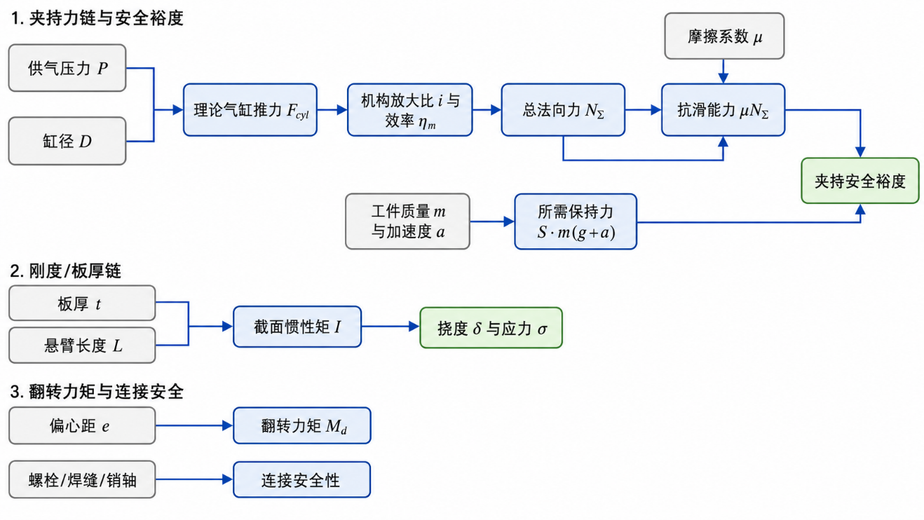
Table 3 summarizes the representative material properties used in the examples.
Table 3 Representative material parameters
| Material | E/GPa | ν | ρ/(kg·m−3) | σy/MPa | α/(10−6·℃−1) | Design notes |
|---|---|---|---|---|---|---|
| Q235 structural steel | 190~210 | 0.27~0.30 | 7 850 | 235 | ≈12 | General-purpose welded plate components |
| Q355 low alloy steel | 190~210 | 0.27~0.30 | 7 850 | 355(≤16);345(>16~40) | ≈12 | Higher strength; stiffness similar to ordinary structural steel |
| 45 steel | 190~210 | 0.27~0.30 | 7 850 | ≈355 | ≈12 | Suitable for pins and trunnions |
| 304 stainless steel | 193 | 0.29 | 8 000 | 215 | 17.3 | Corrosion-resistant; relatively high thermal expansion |
| 6061-T6 aluminum alloy | 68.9 | 0.33 | 2 700 | 276 | ≈23 | Lower mass but substantially lower stiffness |
| TPU 95A-type pad | Approximately 0.14 | — | 1 210 | — | — | Compliant contact layer; account for creep |
| Cast-iron workpiece | 80~160 | 0.2~0.3 | 6 900~7 400 | Varies with grade | 11~14 | Hot parts require insulation and temperature derating |
Note: Typical E, ν, ρ and α ranges for structural steel and grade 45 steel come from the materials appendix [6]. Thickness-dependent Q355 yield strength comes from GB/T 1591-2018 [5]; 304 and 6061-T6 properties come from published material data [7-8]; TPU data are for Elastollan C95A [9]; and room-temperature cast-iron ranges come from the NIST compilation [10]. These values support preliminary design. Use material certificates and appropriate sample inspections for project calculations.
Flexible TPU pads affect load transfer as well as contact feel. Published Elastollan C95A data give a tensile modulus of about 140 MPa, Shore A hardness of about 96, and a creep-modulus/time curve at 23 °C. Sustained gripping and repeated cycling can therefore produce time-dependent compliance and stress relaxation [9]. The NIST compilation gives room-temperature cast-iron Young's modulus of about 80 to 160 GPa and thermal expansion of about 11 to 14 × 10−6·℃−1. Heating alters contact conditions and dimensional relationships. Published hot-casting applications use insulation and cooling air circuits to limit these effects [10][3].
2.3 Friction gripping and cylinder thrust
For two-sided friction gripping, neglecting local contact-pressure variation, the basic slip-resistance condition is:
 (1)
(1)The total normal force required is
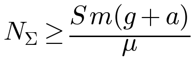 (2)
(2)For symmetric gripping, the normal force on each side is:
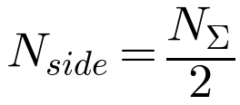 (3)
(3)Distinguish force per jaw from total gripping force. Some standards define clamping force for one side, whereas slip resistance depends on the sum of both normal forces. This study uses NΣ for the total normal force and Nside for the force on one side. T/SZRA 001-2024 recommends calculating payload with a friction coefficient no greater than 0.2 and a safety factor no less than 2 [11]; these values form the conservative preliminary design basis used here.
Theoretical cylinder force follows from pressure and effective piston area. For extension and retraction, respectively:
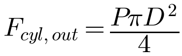 (4)
(4)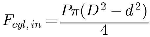 (5)
(5)With a lever, wedge or linkage, the available total normal force is:
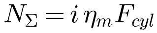 (6)
(6)Here, i is the mechanism force ratio and ηm is the mechanical efficiency accounting for seal, guide and mechanism losses [12]. Determine friction by testing the actual workpiece, surface and contamination condition. Published manufacturer reference values are approximately 0.1 for oily surfaces, 0.2 to 0.3 for wet surfaces, 0.5 for dry wood/metal/glass/stone and 0.6 for rough surfaces [13].
2.4 Bending, deflection, buckling and torsion models
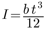
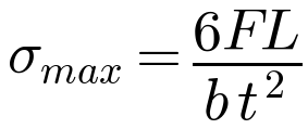
Approximating the main tooling plate as a rectangular cantilever beam gives the second moment of area, maximum root bending stress and free-end deflection:
 (7)
(7) (8)
(8)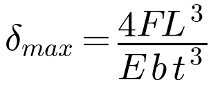 (9)
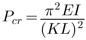
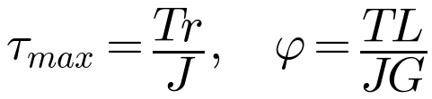
(9)Under the cantilever-beam approximation above, Equations (8) and (9) show that stress decreases with t squared and deflection with t cubed. Where gripping parallelism, positioning accuracy and turning stability are critical, size plate thickness for stiffness first, then verify strength. Slender compression members and thin-walled supports also require Euler buckling checks. Turning shafts, flange sleeves and pins may use the Saint-Venant torsion relationship
 (10)
(10) (11)
(11)Because the elastic modulus of most steels is 190–210 GPa, the difference in E between structural and high-strength steels is far smaller than the difference in yield strength. Accordingly, increasing the steel grade generally reduces deflection much less than increasing plate thickness or shortening the cantilever. By contrast, 6061-T6 has an E of only about 68.9 GPa; with unchanged geometry, aluminum tooling deflection is on the order of 3 times that of steel [6].
2.5 Vacuum gripping model
The normal holding force of vacuum gripping comes from the pressure difference
 (12)
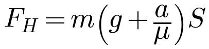
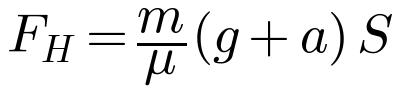
(12)Here, Δp is the effective pressure difference, Aeff is the effective suction area and ηs is the sealing efficiency. Vacuum percentage is measured relative to ambient pressure. At approximately 101.3 kPa sea-level atmospheric pressure, 60% vacuum corresponds to Δp≈60.8 kPa [14]. The following equations cover vertical lifting with horizontal cups, horizontal transfer with horizontal cups, and the unfavorable case of vertical cups carrying a vertical load.
 (13)
(13) (14)
(14) (15)
(15)If n suction cups are used, the theoretical holding force required for a single cup is
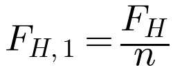 (16)
(16)Evaluate the most unfavorable load case in the complete handling sequence. Use a safety factor of at least 1.5 for smooth, nonporous surfaces and 2.0 or more for porous, rough, oily or heterogeneous surfaces. For porous materials, provide leakage-compensating flow in the 30% to 55% vacuum range; nonporous surfaces can use 55% to 80% vacuum for higher holding force [13,15].
A further example illustrates the effect of orientation: with 6 suction cups of 60 mm diameter, 60% vacuum and ηs=0.85, the theoretical normal force per cup is approximately:
The supplementary example gives a total normal force of approximately 876 N and a static-load ratio of about 3.57 for a 25 kg nonporous panel. Considering vertical lifting alone can therefore overestimate suitability. In the worst orientation, with the suction cups vertical and the load acting tangentially along the panel, μ=0.25, a=1 m/s² and S=2 give a required total holding force of approximately 2 162 N; 6 ϕ60 suction cups are insufficient. Vacuum tooling must therefore be checked throughout the full motion sequence, not only at lift-off.
2.6 Connection checks
Connection checks must address nominal capacity, loosening, hole-bearing failure, fatigue and assembly variation together. The following formulas for average bolt shear stress, hole-bearing stress and average pin shear stress in double shear support first-order screening:
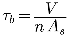 (17)
(17)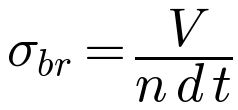 (18)
(18)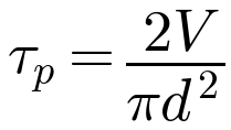 (19)
(19)The effective throat thickness, effective area and nominal shear stress of the fillet weld are
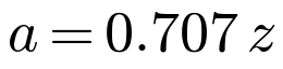 (20)
(20) (21)
(21)Published weld-design guidance commonly approximates the effective throat of a fillet weld as 0.707z [17]. For slip-resistant bolted joints, obtain the slip coefficient from representative surface-condition tests [16].
03Worked examples and finite element analysis
All three examples use a 0.5–0.8 MPa supply window with 0.5 MPa as the conservative design baseline. Preliminary friction-gripping design uses μ≤0.2 and S≥2 [3,11]. Geometry, mechanism efficiency and eccentricity are engineering examples chosen to explain the method, not finalized project parameters.
3.1 Example 1: 50 kg two-sided friction gripping
For a 50 kg workpiece held by a two-sided friction gripper, use a=1.0 m/s², μ=0.20, S=2.0, i=3.0 and ηm=0.85. The calculation proceeds as follows.
Comparison of candidate bore diameters is shown in Table 4.
Table 4 Example 1: cylinder-bore and pressure comparison
| Bore diameter | Pressure/MPa | Fcyl/N | i ηm Fcyl/N | Available force / required NΣ |
|---|---|---|---|---|
| ϕ63 | 0.5 | 1 559 | 3 974 | 0.74 |
| ϕ63 | 0.6 | 1 870 | 4 769 | 0.88 |
| ϕ63 | 0.7 | 2 182 | 5 564 | 1.03 |
| ϕ63 | 0.8 | 2 494 | 6 359 | 1.18 |
| ϕ80 | 0.5 | 2 513 | 6 409 | 1.19 |
| ϕ80 | 0.6 | 3 016 | 7 691 | 1.42 |
| ϕ80 | 0.7 | 3 519 | 8 972 | 1.66 |
| ϕ80 | 0.8 | 4 021 | 10 254 | 1.90 |
At the 0.5 MPa baseline, ϕ63 is insufficient and ϕ80 provides a usable margin. Even with a stable 0.8 MPa supply, ϕ63 has a margin of only about 1.18 and is unsuitable for conservative design. This example shows that the minimum guaranteed pressure must be established before selecting the cylinder bore; the highest possible pressure cannot replace the design baseline.
3.2 Example 2: turning an 80 kg workpiece through 90°
An 80 kg workpiece turns through 90° with center-of-gravity offset e=0.30 m. The turning head and associated components have mass mg=15 kg and offset eg=0.15 m. Use the combined turning design factor κM=2.2, effective lever arm r=0.12 m and mechanical efficiency ηm=0.85.
Comparison of candidate bore diameters is shown in Table 5.
Table 5 Example 2: cylinder-bore and pressure comparison
| Bore diameter | Pressure/MPa | Fcyl/N | Available torque/(N·m) | Available torque / required Md |
|---|---|---|---|---|
| ϕ100 | 0.5 | 3 927 | 400.6 | 0.71 |
| ϕ100 | 0.6 | 4 712 | 480.7 | 0.85 |
| ϕ100 | 0.7 | 5 498 | 560.8 | 0.99 |
| ϕ100 | 0.8 | 6 283 | 640.9 | 1.13 |
| ϕ125 | 0.5 | 6 136 | 625.9 | 1.10 |
| ϕ125 | 0.6 | 7 363 | 751.0 | 1.33 |
| ϕ125 | 0.7 | 8 590 | 876.2 | 1.55 |
| ϕ125 | 0.8 | 9 817 | 1 001.4 | 1.77 |
In this 90° turning example, reducing eccentricity directly reduces load torque. Reducing eccentricity from 0.30 m to 0.20 m with all other conditions unchanged lowers static gravitational torque by approximately 30%. This geometric change reduces the turning burden more directly than upgrading the plate from Q235 to Q355.
3.3 Example 3: 6/8/10 mm plate comparison
Compare 6/8/10 mm thicknesses for the same main plate, modeled as a rectangular cantilever beam. Use effective width b=160 mm, cantilever length L=150 mm, equivalent end load F=1 000 N and E=210 GPa. Table 6 gives the results from Equations (7) to (9).
Table 6 Example 3: plate-thickness comparison
| Plate thickness/mm | I/mm4 | σmax/MPa | δmax/mm | Relative stiffness |
|---|---|---|---|---|
| 6 | 2 880 | 156.3 | 1.86 | 1.00 |
| 8 | 6 827 | 87.9 | 0.785 | 2.37 |
| 10 | 13 333 | 56.3 | 0.402 | 4.63 |
With a process limit of 0.50 mm end deflection, the 10 mm plate meets the requirement, while both the 8 mm and 6 mm plates exceed the limit. Maximum bending stress in the 6 mm plate is 156 MPa, below the typical Q235 yield strength of 235 MPa, yet deflection already exceeds the limit. Passing the strength check does not replace passing the stiffness check.
3.4 Finite element modeling plan
Use analytical models to screen plate thicknesses, cylinder bores and dimensions, then develop a detailed finite element model according to Table 7. Rapid calculations cannot replace simulation of the actual structure.
Table 7 Recommended finite element model
| Item | Recommended settings |
|---|---|
| Model | Three-dimensional solid model of the main plate, flange, lugs, connecting mount and jaw support |
| Material | For structural steel, use representative values E=206 GPa, ν=0.30 and ρ=7 850 kg·m⁻³ within the published ranges; use Table 3 values for 304 or 6061-T6 |
| Elements | Second-order tetrahedral or hexahedral elements; 4–5 mm overall mesh, refined to 1–1.5 mm at hole edges, fillets and lug roots |
| Contact | Frictional jaw/workpiece contact; initially merge welded regions, then use local weld-toe submodels |
| Constraints | Fully constrain the end-flange bolt-hole circle; use pin or coupling constraints at the actual turning axis |
| Loads | Gravity, equivalent gripping normal force, eccentric moment and turning inertia; include lateral impact amplification where relevant |
| Outputs | Total displacement, von Mises stress, maximum principal stress, contact pressure, hole-edge/lug-root stress and connection loads |
| Mesh independence | Refine the local mesh by approximately 30%; accept when key stress and displacement results change by <5% |
Preliminary simulations use structural-steel E and ν values within the typical ranges in the materials appendix: elastic modulus 190–210 GPa and Poisson's ratio 0.27–0.30 [6]. These values support early comparisons and do not imply that grade-specific measurements have been obtained. Figure 2 shows the proposed modeling approach and stress-hotspot locations.
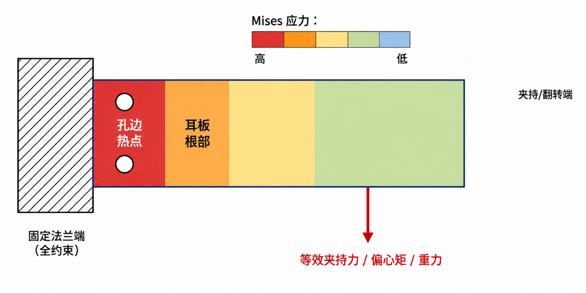
The finite element values below illustrate modeling and comparison methods. Actual projects require verification against their CAD geometry, materials, connections and loads; illustrative results cannot replace analysis or acceptance testing. The examples compare 6/8/10 mm plates, with results in Table 8.
Table 8 Illustrative finite element results
| Plate thickness/mm | Illustrative maximum von Mises stress/MPa | Illustrative maximum displacement/mm | Stress ratio to Q235 | Main hotspots |
|---|---|---|---|---|
| 6 | ≈170 | ≈1.93 | 0.72 | Flange hole edge and cylinder lug root |
| 8 | ≈96 | ≈0.81 | 0.41 | Hole edge transition fillet |
| 10 | ≈61 | ≈0.42 | 0.26 | Local flange connection region |
The illustrative finite element values are of the same order as the analytical results: displacement decreases with t cubed and stress with t squared. Geometric discontinuities at hole edges and lug roots create local stress concentrations with peaks slightly above the beam-model values. Project analysis should at least refine weld toes and cutout corners and recalculate bolt preload and nonlinear contact. High-temperature applications also require thermal loads and thermal derating of contact interfaces.
04Sensitivity analysis, testing and FMEA
4.1 Sensitivity analysis
The models give the following first-order relationships for gripping safety margin, plate deflection and turning moment:
Table 9 summarizes the corresponding sensitivities.
Table 9 First-order sensitivity of main variables
| Variable | Principal response | Mathematical sensitivity | Response to a +10% variable change |
|---|---|---|---|
| Air supply pressure P | Clamping safety margin | +1 | +10% |
| Bore diameter D | Clamping safety margin | +2 | +21% |
| Friction coefficient μ | Clamping safety margin | +1 | +10% |
| Mechanism force ratio i | Clamping safety margin | +1 | +10% |
| Mechanical efficiency ηₘ | Clamping safety margin | +1 | +10% |
| Workpiece mass m | Clamping safety margin | −1 | −9.1% |
| Plate thickness t | Deflection | −3 | −24.9% |
| Cantilever length L | Deflection | +3 | +33.1% |
| Modulus of elasticity E | Deflection | −1 | −9.1% |
| Eccentricity e | Turning moment | +1 | +10% |
Table 9 helps prioritize concept changes. Cylinder bore affects thrust quadratically and is a key geometric input to gripping safety. Plate thickness and cantilever length affect deflection cubically and are central to stiffness checks. Eccentricity directly affects turning torque, so control the center of gravity during layout rather than compensate for unfavorable geometry by increasing end-point pressure.
4.2 Test plan
T/SZRA 001-2024 specifies gripper test conditions of 20±2 °C, 20%–80% relative humidity and 86–106 kPa ambient pressure, with adequate warm-up and statistics from 50 cycles for force control, repeat positioning and peak torque [11]. GB/T 34878-2017 provides a reference for vacuum leakage testing [18]. ASTM E466 constant-amplitude axial fatigue tests may supplement material or representative-component assessment [19]. Table 10 sets out the proposed test sequence.
Table 10 Recommended test sequence
| Stage | Objective | Main equipment/instruments | Outputs |
|---|---|---|---|
| Incoming-material verification | Check plate thickness, material, and heat treatment status | Calipers, ultrasonic thickness gauges, hardness testers, material certificates | Measured thickness t and material condition |
| Clamping force calibration | Establish pressure-clamping force curve | Pressure transducer, tension/compression load cell and data-acquisition system | P-Nside curve |
| Slip-resistance test | Calculate equivalent friction coefficient μeq from the test | Vertical loading tooling, weight/servo loader, displacement sensor | Slip-onset load and μeq |
| Deflection test | Verify plate thickness selection | Laser displacement meter, standard load block | F-δ curve |
| Turning test | Verify 0°/45°/90° pose moment | Torque sensor, inertia simulation block, angle encoder | M-θ curve and overshoot |
| Repeatability test | Measure variation in gripping and positioning | Automatic cycling rig and camera/displacement sensor | Positioning error over 50 repetitions |
| Vacuum gripping test | Verify vacuum retention and leaks | Vacuum meters, flow meters, leak detection equipment | Pressure drop-time curve, effective pressure difference |
| Durability and fatigue | Assess service-life risk | Cyclic test bench; supplemented by coupon fatigue test if necessary | Service-life curve and loosening threshold |
Calibrate static gripping force at 0.5, 0.6, 0.7 and 0.8 MPa, using ≥5 steady-state points at each pressure. Apply slip-test loads to actual workpieces or representative specimens and calculate μeq separately for dry room-temperature, lightly oily, grinding-dust and high-temperature conditions. Use deflection and turning tests to compare analytical and simulation trends, with ≥50 repeatability cycles. Test vacuum retention and leakage at different vacuum levels and derive effective pressure-difference decay from the pressure/time slope. Feed the measured μ, ηm and κM values into the analytical model [11].
4.3 Failure Mode and Effects Analysis (FMEA)
Table 11 gives FMEA recommendations for end-effector tooling. S, O, and D range from 1 to 10, and the risk priority number RPN = S × O × D.
Table 11 End-Effector Tooling FMEA
| Failure mode | Main causes/consequences | S | O | D | RPN | Recommended actions |
|---|---|---|---|---|---|---|
| Frictional slip | Reduced μ, oil contamination or low pressure / dropped workpiece | 10 | 4 | 4 | 160 | Measure μ on the actual workpiece; use a 0.5 MPa baseline; add slip-resistant teeth or coverings |
| Excessive plate deflection | Insufficient thickness or excessive cantilever length / alignment error | 8 | 5 | 4 | 160 | Prioritize thickening or shortening the cantilever; adding ribs instead of just upgrading the steel grade |
| Insufficient turning torque | Underestimated eccentricity or omitted dynamic loads / stalled turning | 9 | 3 | 5 | 135 | Measure the center of gravity first; introduce κM; leave sufficient margin |
| Weld fatigue cracks | Weld toe stress concentration, residual stress/fracture | 9 | 3 | 6 | 162 | Weld-toe dressing, smooth fillets and hotspot fatigue reassessment |
| Loss of bolt preload | Vibration, settlement, thermal cycling/looseness | 7 | 5 | 5 | 175 | Control tightening torque; provide anti-loosening measures and periodic inspection/retightening |
| Pin wear and increased clearance | Frequent turning, insufficient lubrication/deterioration of accuracy | 7 | 4 | 5 | 140 | Replaceable bushing; improve surface hardness |
| Vacuum leakage | Aged cups or uneven surfaces / dropped workpiece | 10 | 3 | 4 | 120 | Vacuum-retention testing, separate vacuum zones and scheduled replacement |
| High temperature seal derating | Insufficient thermal isolation/clamping force drift | 8 | 3 | 6 | 144 | Thermal shielding, cooling air circuits, heat-resistant materials and temperature derating |
The RPN results in this table prioritize loss of bolt preload, weld fatigue cracks, excessive plate deflection and frictional slip. These locations may not have the highest average stress, but accumulated effects of cycling, temperature, contamination and assembly variation can increase failure risk. Match inspection and validation measures to the specific causes.
05Discussion
This framework supports preliminary engineering analysis and does not replace complete calculations for the actual three-dimensional product. Most E, ρ, ν and α entries in the material table are typical values. Formal analysis must confirm them with material suppliers in light of manufacturing processes, defects, temperature and load history. The 304 and 6061-T6 data apply to specified material conditions. Aluminum alloy weld regions may soften, so parent-metal properties cannot represent the post-weld region [6][7-8].
The friction and vacuum models use a first-order approximation of Coulomb friction plus effective pressure difference. Manufacturer guidance requires the friction coefficient to be established by testing original workpieces and vacuum level to account for surface permeability [13-15]. The models compare variable sensitivity, but calibration under actual surface, temperature and contamination conditions remains necessary. For hot castings, evaluate insulation, cooling and seal derating first; increasing clamping force alone is insufficient [10][3].
Illustrative finite element results identify boundary conditions and hotspots; they are not acceptance reports. Project design must further address four areas: weld geometry and residual stress; bolt preload and contact slip; viscoelasticity or creep of flexible pads; and combined thermal and cyclic loads. Review these together with site tests before establishing the design basis.
06Conclusions
(1) Check plate thickness, clamping force and safety margin together. In the model used here, deflection depends on the third power of plate thickness. Where parallelism and low vibration are required, verify stiffness conditions first.
(2) Upgrading steel tooling from Q235 to Q355 mainly increases yield strength and has limited effect on stiffness at unchanged geometry. To reduce deflection, first compare geometric measures such as thicker plates, shorter cantilevers and reduced eccentricity.
(3) In the 50 kg friction-gripping example at 0.5 MPa and μ=0.20, a ϕ80 cylinder bore meets the requirement while ϕ63 is insufficient. Compare bores using the minimum guaranteed supply pressure, not the highest possible pressure.
(4) The 90° turning example for an 80 kg workpiece shows that mass, eccentricity and the combined dynamic-load factor jointly determine turning loads. Eccentricity should receive particular attention during layout.
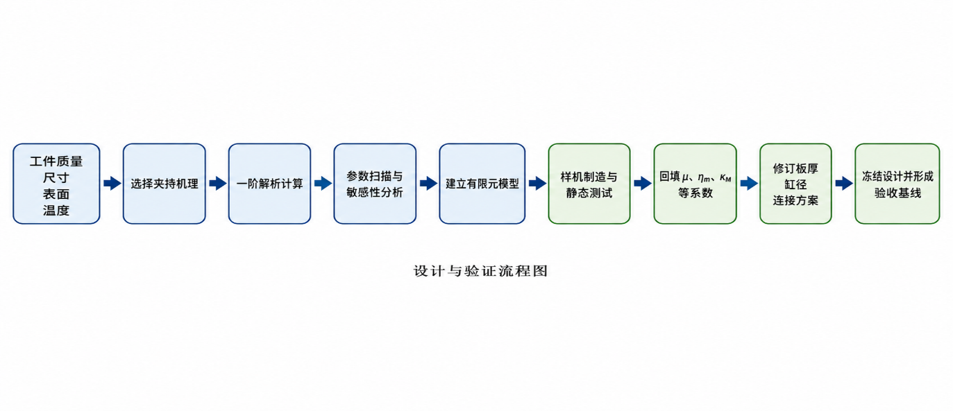
(5) Vacuum gripping must be checked throughout the full motion sequence, with particular attention to tangential slip resistance rather than vertical lifting alone. Friction coefficients and safety factors must be calibrated through actual-workpiece testing. First define the real operating conditions, then use analysis, simulation and testing to determine plate thickness, cylinder bore, connections and surface parameters [6]. Figure 3 shows the process.
References
[1] BELTER J T, DOLLAR A M. Underactuated grasp acquisition and stability using friction based coupling mechanisms[C]//2011 IEEE International Conference on Robotics and Automation. Shanghai: IEEE, 2011: 5895-5900.
[2] Xipeng, Cong Qian, Ye Shaobo, et al. Bionic design and vacuum gripping performance analysis of vacuum suction cups [J]. Journal of Jilin University (Engineering Edition), 2025, 55(1): 382-391.
[3] Jiangsu Aurek Intelligent Technology Co., Ltd. Public technical information on Pneumatic Industrial Manipulators, custom tooling, vacuum lifters and typical application cases [EB/OL]. [2025-06-01]. https://www.aurek.cn/.
[4] National Steel Standardization Technical Committee. Carbon Structural Steel: GB/T 700—2006[S]. Beijing: China Standards Press, 2006.
[5] National Steel Standardization Technical Committee. Low alloy high-strength structural steel: GB/T 1591-2018[S]. Beijing: China Standards Press, 2018.
[6] Southeast University Structural and Bridge Engineering Experimental Center. Commonly used material property parameters [Z]. Nanjing: Southeast University, 2020.
[7] MatWeb. 304 stainless steel material data sheet[EB/OL]. [2025-06-01]. https://www.matweb.com/.
[8] ASM International. Aluminum 6061-T6/6061-T651 material data sheet[EB/OL]. [2025-06-01]. https://www.matweb.com/.
[9] BASF. Elastollan C 95 A (TPU) material data sheet[EB/OL]. [2025-06-01]. https://www.materialdatacenter.com/.
[10] NIST. Thermophysical properties of materials[R/OL]. Gaithersburg: National Institute of Standards and Technology, [2025-06-01]. https://materialsdata.nist.gov/.
[11] Suzhou Robot Industry Association. Rotating electric gripper performance specifications and test methods: T/SZRA 001—2024[S]. Suzhou: Suzhou Robot Industry Association, 2024.
[12] SMC Corporation. Best pneumatics technical data: theoretical output of air cylinders[EB/OL]. [2025-06-01]. https://www.smcworld.com/.
[13] Schmalz. Theoretical holding force of a suction cup[EB/OL]. [2025-06-01]. https://www.schmalz.com/.
[14] Festo. Basic principles of vacuum technology[EB/OL]. [2025-06-01]. https://www.festo.com/.
[15] COVAL. Suction cup performance[EB/OL]. [2025-06-01]. https://www.coval.com/.
[16] KULAK G L, FISHER J W, STRUIK J H A. Guide to design criteria for bolted and riveted joints[M]. 2nd ed. Chicago: AISC/RCSC, 2001.
[17] Purdue University. Weld strength and effective throat: lecture notes of CE 470[Z]. West Lafayette: Purdue University, 2013.
[18] National Technical Committee for Standardization of Vacuum Technology. Vacuum technology valve leakage rate test: GB/T 34878—2017[S]. Beijing: China Standards Press, 2017.
[19] ASTM International. Standard practice for conducting force controlled constant amplitude axial fatigue tests of metallic materials: ASTM E466[S]. West Conshohocken: ASTM International, 2021.