- Within space and cycle-time constraints, high-temperature handling grippers must coordinate load-bearing grip, heat-flow interruption, pneumatic circuit protection, structural stability and ease of maintenance.
- Divide the design into a high-temperature load-bearing zone / thermal isolation zone / low-temperature actuation zone, combining heat-resistant jaws, a ceramic wear layer, a glass-ceramic thermal break, a ceramic-fiber layer, an air-gap thermal break and a reflective shield.
- The composite insulation path calculated in this article has an equivalent thermal conductivity of approximately 0.25 W/(m·K). Under the stated 650℃ simulation conditions, the jaw root is ≤83℃, the cylinder mounting face ≤55℃ and the hose outer wall ≤68℃; heat flux along the main conduction path is approximately 98.7% lower than with a direct metal connection.
- Configure the pneumatic circuit with the air supply away from the heat source, metal tubing near the heat source, secondary hose insulation, components set back and controlled behavior on pressure loss. The calculated thermal protection efficiency of the pneumatic circuit is approximately 76.9% under the temperature conditions specified in this article.
Unit: Jiangsu Aurek Intelligent Technology Co., Ltd. (Lianyungang, Jiangsu) Category: Technical Research Contains complete formulas, tables and finite element results. The full PDF text can be downloaded at the end of the article or in the upper right corner.
00Abstract
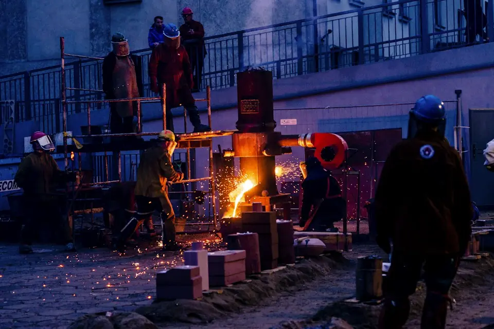
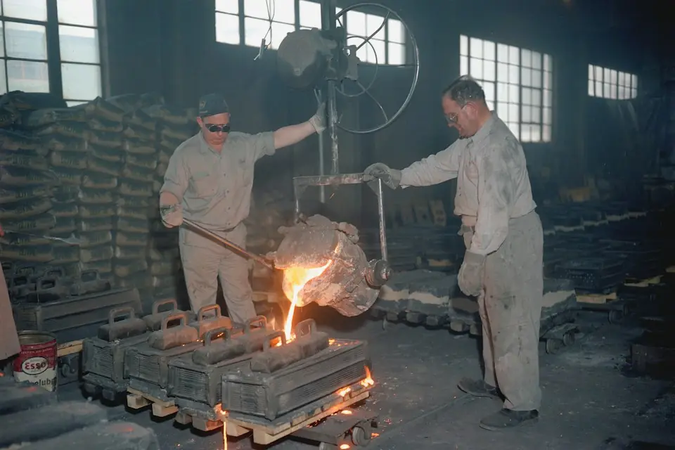
During forging, heat treatment, die casting, sintering and furnace-side handling, heat can travel along the jaws toward the actuator, causing excessive pneumatic system temperature rise, hose aging and failure, false sensor operation and reduced gripping reliability. This article develops a heat-transfer path model for short-cycle handling of hot workpieces and arranges the structure into high-temperature load-bearing, thermal isolation and low-temperature actuation zones. The design addresses material compatibility, layout, insulation paths and pneumatic protection, combining heat-resistant jaws, a ceramic wear-resistant contact layer, a glass-ceramic thermal break, a ceramic-fiber layer, an air-gap thermal break and a radiation reflector. Equivalent thermal conductivity calculations and coupled thermal-structural finite element analysis then compare temperature fields, thermal stress and thermal deformation.
The calculations and simulations in this article give an equivalent thermal conductivity of approximately 0.25 W/(m·K) for the composite insulation path. With a workpiece surface temperature of 650 ℃, a single gripping time of 20 s and an ambient temperature of 35 ℃, the maximum jaw-root temperature remains within 83 ℃, the cylinder mounting face within 55 ℃ and the hose outer wall within 68 ℃. Compared with a continuous direct metal connection, heat flux along the main conduction path decreases by approximately 98.7%, pneumatic circuit thermal protection efficiency is 76.9% and thermal deformation at the gripper tip remains within 0.20 mm. These results compare the structural designs studied here. Actual equipment temperature rise and continuous operating behavior require prototype temperature measurements and cyclic testing.
01Introduction
Manipulators, industrial robots, gantries or dedicated grippers may handle hot workpieces during heating, furnace unloading, transfer, loading and unloading, and movement between processes. Forging, heat treatment, casting, die casting, sintering and downstream steel processing involve strong thermal radiation, significant contact heat transfer, concentrated thermal stress, falling scale and thermal shock. Design gripping force, stiffness and positioning accuracy together with insulation, pneumatic protection and safety controls.
Structural design should first check continuous metal thermal bridges, then the arrangement of hoses, pneumatic components and replaceable insulation parts near the heat source. Increasing only the jaw material's temperature rating does not resolve actuator temperature rise, hose hardening or leakage. Ceramic pads, insulation plates, shields and hose sleeves must also be easy to inspect and replace. Select the design by considering gripping load capacity, heat-flow interruption, pneumatic protection, structural stability and maintenance together.
02Thermal Loads and Design Considerations
2.1 Heat-Transfer Mechanisms
Heat enters the tooling through contact conduction, radiation and convection. Contact conduction carries heat from the workpiece through the jaws. Radiation becomes significant above 500 °C, while hot workshop air, furnace airflow and tooling movement contribute convection. Together they create a nonuniform temperature field, with heat traveling along plates, screws, pins, guides and actuator connections. Hose softening, seal failure, lubricant degradation and sensor faults may occur before structural metal failure, so pneumatic protection and structural insulation must be designed together.
2.2 Problems with existing high-temperature fixture design
Solid heat-resistant steel or stainless steel structures are easy to machine, but a continuous metal connection between hot and cold ends offers low thermal resistance. Where local ceramic spacers are added, their material, thickness and mounting method jointly affect insulation and reliability. Alumina ceramic suits wear resistance, compression and high-temperature contact, but its thermal conductivity is not low, so it should not provide the main insulation by itself. Standard PU, nylon and rubber hoses may harden, crack, age and leak under radiation and hot-air exposure. Structural heat paths, insulation stages, pneumatic routing and control logic must therefore be designed together.
2.3 Composite Insulation and Protective Controls
High-temperature grippers can combine composite insulation, modular maintenance and safety interlocks: heat-resistant alloys carry the hot-end load; low-conductivity materials and air cavities interrupt heat transfer; reflective shields reduce radiation input; pneumatic and sensing components are set back; and lines near the heat source use metal sections and insulating sleeves. Include pressure, temperature and clamping-state signals in the interlocks to provide an integrated thermal, mechanical, pneumatic and control design.
03Tooling Design Method
3.1 Design conditions and target parameters
The analysis considers short-cycle handling of hot forgings / heat-treated parts: after furnace exit, the workpiece is gripped, transferred and placed using a gripper mounted on a robot or gantry, with pneumatic actuation supplying the clamping force. The parameters below are inputs to this article's calculations and design comparison.
| Item | Parameter value | design significance |
|---|---|---|
| Workpiece surface temperature | 650 °C | Corresponding to short-term transportation conditions after being released from the furnace |
| ambient temperature | 35 °C | Consider the high temperature environment in the furnace workshop |
| Workpiece Mass | 80 kg | Medium-sized forgings or heat-treated parts |
| Single clamping time | 20 s | Representative robot or gantry handling cycle |
| cycle frequency | 30~40 cycles/h | Continuous production cycle frequency |
| Operating Air Pressure | 0.6 MPa | Pneumatic actuation pressure |
| Handling Acceleration | 2.0 m/s² | Consider start-stop shock |
| Clamping safety factor | ≥2.5 | Prevent slippage and thermal decay |
| Cylinder mounting surface temperature | ≤60 °C | Protect seals and lubrication status |
| Hose Outer-Wall Temperature | ≤70 °C | Prevent hose thermal aging |
| Thermal deformation of tooling end | ≤0.25 mm | Ensure repeated positioning and clamping stability |
Table 1 Typical high temperature workpiece handling conditions parameters
3.2 Clamping force calculation and structural load-bearing requirements
When using double-sided clamping, the normal clamping force required by the single-sided clamping jaw can be preliminarily checked according to the friction clamping model:
where Fn is the one-sided normal clamping force (N), S is the safety factor, m is the workpiece mass (kg), g is the acceleration of gravity, a is the acceleration of the moving load (m/s²), and μ is the high-temperature contact friction coefficient. Assuming S=2.5, m=80 kg, a=2.0 m/s², μ=0.35, the required clamping force on one side is approximately 3371 N; Considering the oxide scale, vibration impact, clamping jaw wear and friction coefficient fluctuation, the rated clamping force of one side in engineering design should not be less than 4.2 kN. High-temperature workpieces should not rely entirely on friction. V-shaped grooves, step limits, envelope supports or bottom supports should be used first, so that the clamping force and geometric limits share stability.
3.3 Functional partition design principles
Arrange the gripper in three functional zones. The high-temperature load-bearing zone contacts or approaches the workpiece and provides gripping, heat resistance and oxidation resistance. The thermal isolation zone, between the jaws and actuator, reduces heat flux, interrupts thermal bridges and accommodates thermal stress. The low-temperature actuation zone houses cylinders, guides, valve manifolds, sensors and the robot connection, away from direct thermal radiation. Clearly separate load-bearing, insulation and actuation functions at the connections to avoid continuous metal heat-transfer paths.
3.4 Material selection and structural layout
| parts | Recommended materials | Main function | Reason for selection |
|---|---|---|---|
| Gripper-jaw front load-bearing member | Inconel 625 or heat resistant stainless steel | Withstand clamping loads and face high temperature radiation | High temperature strength, oxidation resistance, corrosion resistance |
| Workpiece contact layer | 96% alumina ceramic | Wear-resistant, pressure-resistant, reduces metal adhesion | Suitable for replaceable wear pads and not used as the sole primary insulation layer |
| Thermal-Break Block | Macor Glass-Ceramic | Block heat transfer from the clamping jaw to the mounting base | Low conductivity and machinability for locating thermal breaks |
| Flexible insulation | ceramic fiber blanket | Reduce cavity conduction and radiation heat transfer | Low thermal conductivity, low heat capacity, thermal shock resistance |
| thermal insulation cavity | Air-Gap Structure | Weaken continuous solid thermal bridges | Simple, lightweight structure compatible with fiber insulation |
| reflective shield | 304/316 stainless steel sheet | Shield radiation and protect the pneumatic circuit | Easy to form, disassemble and replace |
| Low-Temperature Mounting Bracket | Stainless steel or low alloy steel | Provide installation and load-bearing stiffness | Good processability, but continuous thermal bridges need to be avoided |
| Pneumatic circuit near heat source | 316 stainless steel pipe or stainless steel braided PTFE hose | Improve temperature resistance and mechanical damage resistance | Suitable for short distance pipelines close to heat sources |
Table 2 Materials and functions of main components of the fixture
Along the heat-flow path, the structure comprises heat-resistant alloy load-bearing jaws, replaceable alumina ceramic wear pads, a Macor glass-ceramic thermal break, an air-gap thermal break and a ceramic-fiber infill layer, with a thin stainless steel reflective shield outside. Include screws, locating pins and clamping plates in the thermal-bridge review; prevent screws at the hot end from extending directly into the cold mounting base. Depending on connection requirements, use staged fastening, insulating bushings, reduced-shank screws or locally reduced cross-sections. Preload ceramic pads through face contact and retain them mechanically; do not rely on adhesives to carry shear at high temperature.
04Thermal insulation performance analysis and optimization
4.1 Heat transfer model
For the preliminary calculation, simplify the main heat-transfer path from jaw to mounting base as flat layers in series and estimate heat flow using a steady-state conduction model:
Radiation heat transfer is estimated as follows:
Here Q is the heat-transfer rate (W), keq is equivalent thermal conductivity, ε is surface emissivity and σ is the Stefan–Boltzmann constant. Radiation from a 650 °C workpiece also heats hoses, sensors and thin structures; provide a reflective shield alongside contact insulation.
4.2 Calculation of equivalent thermal conductivity of composite insulation structures
Taking the equivalent heat transfer path on one side as an example, take the heat transfer area A=1200 mm², the high temperature side is 650 °C, and the low temperature side target is 35 °C. The parameters of the composite insulation layer are as follows.
| Layer | material or structure | Thickness/mm | Thermal conductivity W/(m·K) | Thermal resistance L/k /(m²·K/W) |
|---|---|---|---|---|
| 1 | Inconel 625 heat-resistant gripper part | 3 | 17.5 | 0.00017 |
| 2 | Alumina ceramic wear pads | 5 | 24.7 | 0.00020 |
| 3 | Macor glass ceramic insulation blocks | 8 | 1.46 | 0.00548 |
| 4 | ceramic fiber insulation | 12 | 0.16 | 0.07500 |
| 5 | Equivalent Air-Gap Layer | 4 | 0.085 | 0.04706 |
| total | Composite Insulated Path | 32 | 0.25 (equivalent) | 0.12791 |
Table 3 Composite insulation path parameters
From equation (3), the equivalent thermal conductivity of the composite insulation path is obtained:
Heat flow density per unit area:
One-sided heat transfer:
At the same total thickness, the direct continuous-metal design assumes a mean thermal conductivity of 20 W/(m·K), giving a calculated heat flux of approximately 3.84×10⁵ W/m². The corresponding calculated value for the composite path is approximately 98.7% lower. In this model, the Macor thermal break, ceramic-fiber layer and air-gap thermal break provide the main thermal resistance. The more thermally conductive alumina ceramic provides contact wear resistance and is not the sole primary insulation layer.
4.3 Boundary conditions for heat flow simulation
| Boundary Condition | value |
|---|---|
| Workpiece contact surface temperature | 650 °C |
| Workshop ambient temperature | 35 °C |
| natural convection heat transfer coefficient | 8 W/(m²·K) |
| High temperature workpiece radiant emissivity | 0.75 |
| Metal shield outer surface emissivity | 0.35~0.45 |
| clamp contact time | 20 s |
| Steady state check time | 1800 s |
| Air-hose outer surface safety targets | ≤70 °C |
| Cylinder mounting surface safety objectives | ≤60 °C |
Table 4 Boundary conditions for heat flow simulation
Coupled thermal-structural analysis first calculates the temperature field, then imports it into the structural model with gripping force, gravity, dynamic acceleration and boundary constraints. Focus on temperatures at the jaw root, cylinder mounting face and hose outer wall, as well as thermal stress around holes in the insulating blocks and thermal displacement at the tip.
4.4 Finite element analysis results
| Design | Structural description | Maximum temperature at the root of the clamp jaw/°C | Maximum temperature of cylinder mounting surface/°C | Maximum temperature of outer wall of air line/°C | Maximum equivalent stress/MPa | End thermal deformation/mm | Evaluation |
|---|---|---|---|---|---|---|---|
| A | 304 stainless steel overall direct connection, no protection | 312 | 186 | 156 | 221 | 0.46 | Does not meet pneumatic safety requirements |
| B | Metal gripper + single layer ceramic pad | 168 | 104 | 121 | 138 | 0.29 | Improved, but pneumatic temperatures remain excessive |
| C | Composite insulation structure + reflective shield | 83 | 54 | 62~68 | 118 (metal zone) / 42 (ceramic thermal-break zone) | 0.18 | Meets the temperature and deformation criteria in this model |
Table 5 Comparison of thermal-structural analysis results of different structural schemes
Under the simulation boundaries used here, Design C reduces the jaw-root temperature by approximately 73.4%, cylinder mounting-face temperature by approximately 71.0%, hose outer-wall temperature by approximately 56%–60% and tip thermal deformation by approximately 60.9% relative to Design A. Most of the temperature drop occurs across the Macor insulating block, ceramic-fiber layer and air-gap thermal break. Thermal stress concentrates around screw holes in the insulating block, jaw step transitions and the edges of ceramic-pad clamping plates. In the model, the maximum thermal stress in the Macor block is approximately 42 MPa, within the assumed safe range; maximum equivalent stress at the metal jaw root is approximately 118 MPa, below the allowable value used. Tip thermal deformation is 0.18 mm, below the design limit of 0.25 mm.
4.5 Key points for optimization of thermal insulation structure
- Reduce continuous metal thermal bridges: Keep hot-end screws from extending directly into the actuator mounting base. Use staged fastening, insulating bushings or reduced-section connections where appropriate.
- Separate load support and insulation: Heat-resistant alloys carry load, ceramic pads resist contact wear, Macor and ceramic fiber interrupt heat flow, and reflective shields reduce radiation.
- Control ceramic tensile stress: Use face-contact preload and avoid sharp-edge loading. Chamfer and round mounting holes to limit local stress in components with limited tensile and impact resistance.
- Set up maintainable insulation modules: Ceramic pads, thermal insulation fibers, reflectors and air-line sheaths are designed as modular wearing parts for quick replacement.
05Pneumatic-circuit protection design
5.1 General principles of pneumatic circuit protection
Develop the pneumatic circuit alongside the structural concept, following the principles of keeping the air supply away from the heat source, using metal near the heat source, providing secondary hose insulation, locating actuators in the low-temperature zone and controlling pressure-loss behavior. At hose and fitting locations vulnerable to thermal failure, combine routing on the shielded side, metal transition tubes, insulating sleeves and reflective shields.
5.2 Safety measures for compressed-air supply interface
The compressed-air supply interface should be arranged above the fixture, on the back side of the robot flange or at the fixed end of the equipment, with a straight-line distance of not less than 300 mm from the high-temperature workpiece; when space is limited, use a reflector, heat shield or structural shield to avoid direct radiation.
| Air supply interface unit | design measures | Main function |
|---|---|---|
| Manual stop valve | Set lock function | Reliably isolate the compressed-air supply during maintenance |
| Filter pressure reducing valve | The pressure is stable at 0.55~0.65 MPa | Ensure stable clamping force |
| Check Valve | Prevent pressure backflow | Avoid abnormal pressure relief |
| Pressure-Holding Valve or Small Air Receiver | Maintain short-term clamping after shutting off air | Retain the load during the specified response period |
| Safety relief valve | Release in case of overpressure | Prevent pneumatic line from bursting |
| pressure sensor | Real-time detection of clamping pressure | Interlocked with robot safety logic |
| Temperature tag or thermocouple | Monitor interface area temperature | Identify local heat accumulation |
Table 6 Safety measures for compressed-air supply interface
Use grip-retention priority in the pneumatic logic. After power, air-supply or control-signal failure, maintain gripping or mechanical locking. Permit release only after the workpiece is in the safe placement area, support is established and air pressure is stable.
5.3 Air-hose insulation design
Protect the hose in three stages. Route it along the low-temperature, shielded side, outside direct jaw radiation. Within 100–300 mm of the heat source, use suitable 316 stainless steel tubing, corrugated stainless steel tubing or stainless steel-braided PTFE hose, then transition to ordinary flexible tubing farther away. Add ceramic-fiber or silicone-coated fiberglass sleeves, or corrugated stainless steel protection, with a removable external reflector.
The thermal protection efficiency of the air line is evaluated as follows:
Using hose outer-wall temperatures of 178 ℃ unprotected and 68 ℃ protected, with an ambient temperature of 35 ℃, the calculated thermal protection efficiency is 76.9%. The protected temperature is below the 70 ℃ target set in this article. Pneumatic circuit behavior during continuous handling still requires prototype temperature measurements and cyclic testing.
5.4 Thermal protection design of pneumatic components
Place cylinders in the low-temperature zone and transmit motion through heat-resistant links, levers or insulated push rods. Provide an insulating sleeve and thin metal thermal cap between the rod and hot jaw. Locate valves and manifolds behind the robot wrist, beside the gantry slide or at a fixed remote point, leaving only short lines at the tooling. Where furnace radiation is strong, a 20–40 L/min purge curtain outside the shield may be used; direct it away from scale splash. Monitor hot-zone lines with temperature indicators and stop for inspection above 80 °C.
06Safety Assessment and Industrial Applications
6.1 Failure modes and risk control
Assess four risk categories—mechanical, thermal, pneumatic and control—and link each to its failure causes, consequences, control measures and inspection indicators.
| failure mode | Possible Causes | main consequences | control measures | Suggested quantitative indicators |
|---|---|---|---|---|
| Workpiece slips | Insufficient clamping force, oxide scale falling off, air pressure drop | Equipment damage or personal injury | Adequate safety factor, V-groove or mechanical support, pressure-holding valve | Single-jaw force ≥4.2 kN; prohibit handling below 0.45 MPa |
| Thermal aging of air line | The air hose is close to the heat source and lacks heat insulation cover | Air leakage, pipe burst, clamp pressure loss | Shielded-side routing, metal tubing and insulating sleeves | Air-line outer wall ≤70 °C |
| Cylinder seal damage | The temperature of the cylinder rises too high and the piston rod conducts heat | Sluggish movement and reduced clamping force | Rear-mounted cylinder, heat-insulating push rod, reflective cover | Cylinder mounting surface ≤60 °C |
| Ceramic pad cracked | Thermal shock, point contact, pressure plate stress concentration | The contact surface is damaged and the clamping is unstable. | Surface contact preload, rounded corner transition, replaceable modules | Ceramic tensile stress safety factor ≥3 |
| Thermal deformation of gripper jaws | The temperature gradient is too large and the structure is asymmetrical | Clamping offset load and positioning error | Symmetrical insulation, adding stiffeners, and simulation verification | End thermal deformation ≤0.25 mm |
| Personnel burns | Missing protective cover and exposed high temperature surface | personal injury | Heat shields, warning signs, interlocking areas | Contactable outer surface ≤55~60 °C |
| Sensor malfunction | High temperature, heat radiation, cable aging | Action logic error | Set-back sensors, metal conduit and electrical insulation | Sensor mounting surface ≤50 °C |
Table 7 Main failure modes and control measures
6.2 Industrial application scenarios
Select the structure for the workpiece and heat-source characteristics. Forging loading and unloading of round bars, billets and die forgings can use heat-resistant alloy jaws, ceramic pads and mechanical support steps. Heat-treatment furnace unloading of baskets, trays and shaft/disc parts emphasizes radiation shielding and remotely routed air lines. Die-casting / casting post-processing requires protection against scale, flash and hot-particle impact, with replaceable reflective shields. For six-axis robot end effectors, verify mass, center-of-gravity offset and heat transfer together, positioning cylinders, valve manifolds and sensors behind the flange where practicable. Where truss or gantry space permits, thicker insulating cavities and external valve enclosures may be used.
6.3 Project implementation suggestions
- Establish a heat source inventory during the design phase: Record the workpiece and furnace mouth temperature, residence time, oxide scale splash direction, robot path and contact area.
- Prototype temperature measurement: Use infrared measurement and thermocouples at the jaw root, cylinder mounting face, hose outer wall, valve-manifold plate and sensor mount. Record temperature rise over at least 2 hours of continuous operation.
- Cycle life test before mass production: At least 10000 no-load cycles and 2000 simulated heat-source clamping cycles; inspect ceramic pads for cracks, fasteners for loosening, air lines for hardening, seals for leakage, and repeatability.
- Routine maintenance: Inspect ceramic pads each shift, insulation fiber weekly and hose sleeves monthly; replace damaged parts. Stop and investigate when hose temperature exceeds 80 °C or the cylinder mounting face exceeds 70 °C.
- Safety interlocks: Combine gripping, pressure, robot-position and workpiece-support feedback. Inhibit high-speed handling if pressure is low, gripping is incomplete or temperature exceeds its limit.
07Conclusion and outlook
Conclusions: (1) Arrange the gripper in high-temperature load-bearing, thermal isolation and low-temperature actuation zones, with clear load-bearing and heat-protection responsibilities. (2) The design comparison in this article supports composite insulation for controlling heat flow. (3) The calculated equivalent thermal conductivity is approximately 0.25 W/(m·K), with heat flux along the main path approximately 98.7% lower than a direct metal connection. (4) Under the stated 650 ℃ simulation conditions, the cylinder mounting face is ≤55 ℃ and the hose outer wall ≤68 ℃, meeting the article's temperature targets; actual continuous-operation performance requires prototype verification. (5) Design pneumatic protection and structural insulation together; raising component temperature ratings alone is insufficient. (6) Use maintainable modules for critical insulation parts and inspect and replace them as specified.
Further work: Further studies can address thermal fatigue life at ceramic–metal interfaces, measured comparisons of insulation material combinations, and temperature, air-pressure and gripping-force feedback. Selection databases, predictive maintenance and digital safety assessments need corresponding test data and monitoring results as their foundation.
08References
- Yang Shiming, Tao Wenquan. Heat Transfer[M]. Beijing: Higher Education Press, 2019.
- Wen Bangchun. Mechanical Design Manual[M]. Beijing: Machinery Industry Press, 2018.
- Cheng Daxian. Mechanical Design Atlas[M]. Beijing: Chemical Industry Press, 2017.
- ISO 4414:2010. Pneumatic fluid power—General rules and safety requirements for systems and their components[S].
- ASM International. Heat-Resistant Materials[M]. Materials Park: ASM International, 1997.
- Incropera F P, DeWitt D P, Bergman T L, et al. Fundamentals of Heat and Mass Transfer[M]. Hoboken: Wiley, 2011.
- Wang Jianhua, Liu Zhifeng, Li Tao. Analysis of thermal conductivity and structural reliability of mechanical fixtures under high temperature conditions [J]. Mechanical Design and Manufacturing, 2021(8): 112-116.
- Zhang Guoliang, Ma Huizhong. Research on high temperature protection design of industrial robot end tooling units [J]. Manufacturing Automation, 2022, 44(6): 85-90.
- Li Haifeng, Zhou Ming, Chen Xiaodong. Application progress of ceramic insulation materials in industrial equipment [J]. Materials Herald, 2020, 34(12): 12045-12052.
- Zhao Yong, Sun Tao. Research on reliability design methods of pneumatic systems in high temperature environments [J]. Hydraulics and Pneumatics, 2021(9): 98-103.
- aurek.cn. Jiangsu Aurek custom tooling and automation equipment related information [EB/OL]. Access date: 2026-06-07.
- Jiangsu Aurek Intelligent Technology Co., Ltd. Corporate public information and business scope information [EB/OL]. Access date: 2026-06-07.