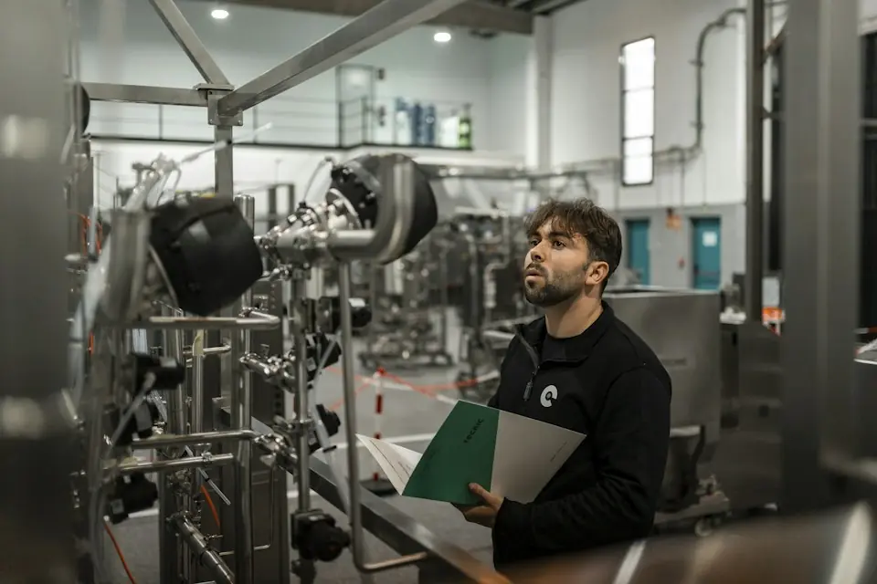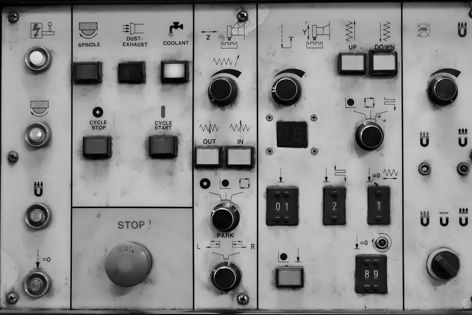
- Site commissioning checks installation condition and verifies that the equipment, tooling and safety functions suit the actual workpiece and workstation.
- Commissioning sequence: installation checks → air connection → unloaded tests → load balancing → tooling/vacuum tests → protective-function tests.
- Adjustment of load balancing, pneumatic circuits, balancing valves, protective devices and load-bearing structures is the responsibility of the manufacturer or qualified personnel. Do not modify them independently.
- Use the parameters specified on the equipment nameplate and in the technical proposal, and record settings, test results and training in the site documentation.
Installation location, air-supply condition, working radius, workpiece weight, tooling orientation, operator position and the surrounding layout all affect operation. Site commissioning is still required after factory inspection, covering the actual pickup and placement sequence under site conditions.
01Site commissioning scope
Commissioning should check the mechanical structure, pneumatic system, load balancing, tooling motion, vacuum gripping and safety functions. For equipment with custom tooling, suction cups or a turning mechanism, verify gripping, lifting, movement and placement throughout the actual working envelope, and check the protective functions fitted.
02Preparation for commissioning
Before commissioning, check that the foundation, column, arms, slewing structure, rails or suspension structure are secure. Clear the work area and exclude uninvolved personnel. For pneumatic equipment, also check interfaces, supply condition, air cleanliness, connections and filter-regulator configuration. Prepare the relevant workpiece, tooling, layout dimensions, technical proposal, packing documentation and acceptance records.
03Commissioning procedure
Installation checks
Verify correct installation of the base, column, connection flanges, arm structure, rotary components, rails, and suspended structures; confirm fasteners are secured, travel-limit structures are complete, and the equipment does not interfere with nearby machine tools, conveyors, racks, guards, or personnel aisles. For column-mounted equipment, focus on the foundation, levelness, column verticality, and operating-radius envelope. For overhead-mounted or rail-mounted equipment, focus on the overhead load-bearing structure, suspension points, rail straightness, and travel range.
Air connection and pneumatic checks
The manufacturer or qualified personnel should connect the air supply. Check hoses, fittings, valves, filter-regulators, handles, cylinders and associated circuits for correct connection, leaks, kinks, loose fittings and abnormal responses. Do not independently modify circuits, balancing valves, control valves or safety devices.
Unloaded motion tests
Without a workpiece, test lifting, lowering, slewing, extension/retraction, travel, limits and return. Check for binding, unusual noise, uneven rotation, drift or incorrect speed. Resolve installation, pressure, connection or interference faults before loaded tests.
Load balancing
The manufacturer or qualified personnel should adjust the balance according to workpiece weight, tooling weight and working radius. Test at different heights, extensions and angles, observing stability during lifting, holding position, movement and placement. Record the actual settings within the equipment's permitted range.
Custom-tooling tests
First test jaw opening and closing, locating contact, cylinders, locking mechanisms, handle buttons, release logic and drop-prevention measures without a workpiece. Then test with a workpiece under the low-risk trial-gripping requirements. If gripping is unstable or there is positioning error, interference or abnormal release, have qualified personnel correct the issue and retest.
Vacuum-gripping tests
Use the actual workpiece to check suction-cup contact, vacuum build-up and release, gripping position and lifting condition. Consider material, roughness, flatness, porosity, oil and dust. Verify vacuum pressure, holding capacity and safety margin against the equipment's technical requirements, and retain the test records.
Safety protection, rotation and braking tests
Test travel limits, drop prevention, air-loss protection, protection against incorrect operation, emergency stops and release logic as fitted. For slewing equipment, verify range, damping, braking and positioning. Keep the swept area clear of pedestrian aisles, forklift routes and other equipment motion. Reassess safety zones if the layout changes.
04Commissioning checklist
| Step | Task | Key checks | Precautions |
|---|---|---|---|
| 1 | Installation checks | Base, column, arm, rails, fasteners and travel limits | Complete installation checks before testing motion |
| 2 | Air connection | Supply pressure, fittings, valves and filter-regulator | Use nameplate and technical-design parameters; record site settings |
| 3 | Pneumatic line inspection | Leaks, loose fittings and kinked hoses | Do not modify circuits or valves independently |
| 4 | Unloaded motion tests | Smooth lifting, lowering, slewing, extension/retraction and travel | Stop and investigate binding or abnormal response |
| 5 | Load balancing | Settings matched to workpiece and tooling weight; stable holding and movement | Do not adjust the balance valve and load-bearing structure without permission |
| 6 | Custom-tooling tests | Jaws, location, locking, release and drop prevention | Test without a workpiece first, then with one |
| 7 | Vacuum-gripping tests | Cup contact, pickup, lifting and release | Workpiece surface conditions will affect the vacuum-gripping performance |
| 8 | Protective-function tests | Limits, drop prevention, air-loss protection and prevention of incorrect operation | Do not remove or bypass safety devices without authorization |
| 9 | Slewing and braking tests | Rotation range, braking effect, positioning status | Avoid interference with personnel passages and peripheral equipment |
| 10 | Training and handover | Operating methods, inspection requirements and abnormal-condition procedures | Complete handover records after training |
05Operator training and handover records
After commissioning, the manufacturer or qualified personnel should provide equipment-specific training on the structure, handles, pickup and placement, balanced operation, tooling and suction cups, daily checks and abnormal shutdown. Training must identify daily inspection points and the pneumatic circuits, balancing valves, safety devices, load-bearing structures and tooling connections that must not be adjusted without authorization.
Demonstrate pickup, lifting, movement, placement and reset using the actual workpiece. Record the equipment number, workpiece information, commissioning condition, trainees and site results. If workpiece weight, dimensions, material or the handling path changes, contact AUREK to reassess suitability.