- Manipulator parameters establish load capacity, radius and stroke. Tooling selection checks gripping, surface protection, deformation limits and fixture location.
- The seven types—side clamping, hooks, vacuum cups, foam grippers, internal expansion, support and turning tooling—have distinct contact and motion conditions. Similar appearance alone does not make them interchangeable.
- Compare solutions in three steps: record the workpiece itself, break down the process motions, then verify the site conditions.
- Rough, perforated, permeable, oily or deformed workpieces, and those with too little contact area, are often unsuitable for conventional vacuum gripping.
Pneumatic industrial manipulators, pneumatic balancers and vacuum lifters provide load capacity and motion range; their tooling applies those capabilities to the workpiece. Tooling selection must check contact, support, surface protection, deformation limits and positioning, rather than rely only on manipulator load capacity, radius or stroke.
01Why tooling needs its own selection assessment
The force relationship between workpiece and equipment changes with tooling type. Evaluate side clamping for boxes, housings and die-cast parts; hooks for workpieces with reliable lifting holes or lugs; vacuum gripping for sheets, cartons and flat parts; and internal expansion for bored, ring-shaped and cylindrical parts. Define permitted contact and load-bearing locations before selecting the structure.
02Common tooling types
- Side-clamping tooling: for regular parts with reliable gripping faces on both sides, such as automotive parts, boxes, housings and die castings. Check allowable clamping force, indentation and scratching limits, and deformation risks.
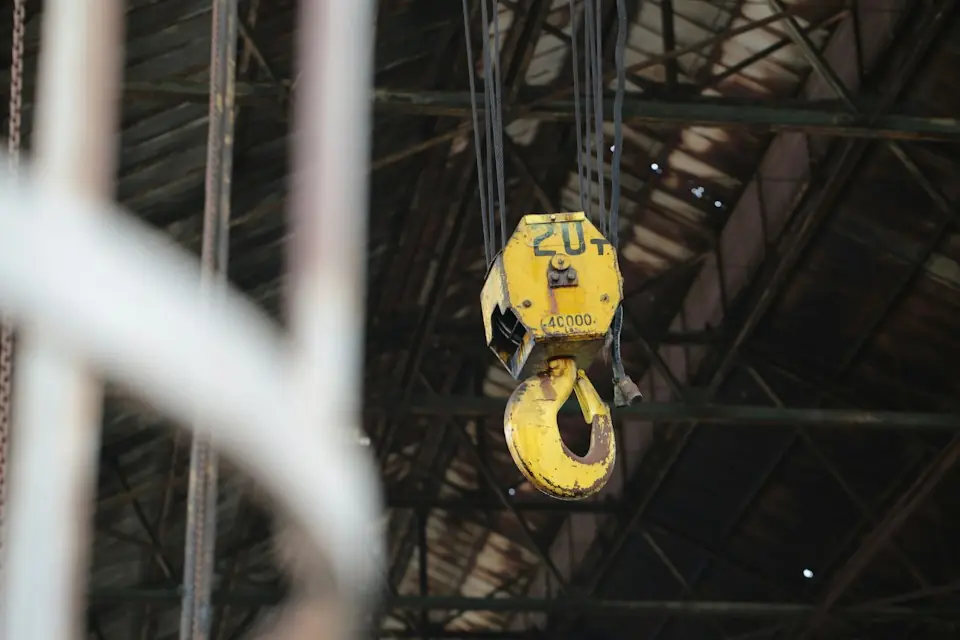
- Hook tooling: for lifting holes, lugs, attachment points or holes designed to carry loads, generally with a direct pickup and placement path. Verify lifting-point strength, center of gravity and anti-disengagement measures. Ordinary holes must not be treated as load-bearing points.
- Vacuum-cup tooling: for relatively flat, airtight sheets, boxes, glass, metal sheets and plastic panels, including use with vacuum lifters. Check how holes, oil, dust, texture and deformation affect holding.
- Foam-gripper tooling: may be evaluated for cartons, packages and some panels with slightly uneven surfaces, mild texture or shape variation. Permeability, dust and holding stability still require verification.
- Internal-expansion tooling: for bored, ring-shaped, cylindrical or stator-type parts, reducing contact with external surfaces. Check inner-wall strength, expansion stroke, release clearance and positioning accuracy.
- Support tooling: for workpieces that can be supported underneath but whose surfaces are unsuitable for clamping or vacuum gripping. Bottom support reduces contact-damage risks, but must prevent sliding and overturning and provide withdrawal clearance.
- Turning tooling: for inversion, reorientation, inclined assembly and angular adjustment, combined with side-clamping, internal-expansion, support or vacuum structures. Check center of gravity, travel limits and operating logic throughout the orientation change.
03Comparing clamping, hook, vacuum and internal-expansion tooling
First record workpiece weight, dimensions, shape, material and surface. Weight guides load capacity; dimensions define the frame and clearances; shape and permitted contact areas guide the choice of clamping, internal expansion, suspension, vacuum or support.
Then break down the process motions. Turning, positioning, assembly or reaching into machinery require coordinated checks of mechanisms, guides, button logic and interference. Specify indentation, scratching, electrostatic and deformation limits for precision, coated and electronic parts.
Finally, verify a stable air supply, the vacuum source, and sensing, interlock and control interfaces. Define the application range and configuration in the technical proposal using workpiece samples and site conditions.
04Workpieces unsuitable for conventional vacuum gripping
Conventional vacuum gripping requires suitable surfaces and sealing. It must not be applied directly to workpieces that are rough, perforated, permeable, heavily dusty or oily, markedly deformed or have too little contact area. Hot workpieces also require checks of cup material, contact time and site safety.
For cartons, verify board strength, permeability and collapse risk. For uneven die-cast parts, blanks or castings, evaluate clamping, internal expansion, support or combined tooling rather than relying solely on conventional suction cups.
05Tooling comparison
| Tooling type | Suitable workpieces | Main advantages | Precautions | Typical applications |
|---|---|---|---|---|
| Side-clamping tooling | Boxes, housings, die castings and regularly shaped parts | Direct clamping with a broad range of applications | Confirm whether the workpiece is pressure-sensitive, scratch-sensitive, or deformation-prone | Automotive parts handling and housing loading/unloading |
| Hook tooling | Workpieces with lifting holes, lifting lugs or reliable hanging points | Relatively simple structure and convenient pickup and placement | Check lifting-point strength, center of gravity and anti-disengagement measures | Lifting and transportation of motor components and machined parts |
| Vacuum-cup tooling | Sheets or boxes with flat, sufficiently airtight surfaces | Soft contact, suitable for flat surface handling | Not suitable for obvious air leakage, oil stains, and rough surfaces | Sheet, carton and flat-part handling |
| Foam-gripper tooling | Slightly uneven or textured surfaces and packaging workpieces | Accommodates some surface variation | Check permeability, dust and holding stability | Handling of cartons, packages and some boards |
| Internal-expansion tooling | Tubular, ring-shaped, workpieces with inner holes | Less contact with the outer surface and better positioning | Check inner-wall strength and release clearance | Motor stator handling and sleeve workpieces |
| Support tooling | Workpieces that can be supported underneath and are unsuitable for clamping or vacuum gripping | Lower risk of surface damage | Prevent sliding and tipping; check the withdrawal path | Assembly assistance, special-shaped parts transfer |
| Turning tooling | Workpieces requiring inversion, reorientation or inclined assembly | Enables orientation adjustment | Assess center of gravity, travel limits and button logic | Loading and unloading, turning assembly, production line handling |
06Tooling selection information checklist
| Item | Information to provide | Impact on tooling design |
|---|---|---|
| Workpiece weight | Single piece weight and weight fluctuation range | Affects fixture load, manipulator load and safety margin |
| Workpiece dimensions | Length, width and height, appearance drawings, physical photos | Tooling structure, opening dimensions and clearance |
| Workpiece shape | Whether it is regular, whether there are holes, hanging points or clamping surfaces | Choice of clamping, hook, internal-expansion, support or vacuum tooling |
| Workpiece material | Metal, plastic, carton, plate, casting, etc. | Affects contact materials, clamping force and protection methods |
| Surface condition | Flatness, roughness, oil, dust and holes | Suitability for vacuum cups or foam grippers |
| Workpiece characteristics | Sensitivity to pressure or scratches, deformability and high temperature | Affects fixture contact methods and protective structures |
| Process movements | Turning, positioning, assembly and loading/unloading requirements | Turning mechanism, locating features and button logic |
| Site conditions | Supply pressure, vacuum source, equipment envelope and access routes | Affects pneumatic circuit control, installation methods and safety logic |
| Operation mode | Operator position, handle orientation and button-use preferences | Handle arrangement, ergonomics and ease of use |