- Determine working radius from the pick and place points and complete path, while checking payload, gripper weight, operating feel, stability and safe clearance.
- Arm length is a structural dimension; working radius is the usable range, affected by rotation angle, tooling length, mounting position and obstacles.
- Excessive reach can increase load moment, inertia, footprint and interference risk, while reducing stability.
- Selection inputs include the site layout, workpiece parameters, gripper type and complete movement sequence, establishing the usable radius and clearance requirements.
The working radius must cover actual pick-and-place and detour paths while accounting for load moment, starting and stopping effort, and surrounding space. An undersized radius limits access; an oversized radius may increase inertia, footprint and interference. Establish the mounting center and working path first, then select reach and rotation settings.
01What working radius means
Working radius generally means the horizontal coverage from the rotation center or mounting datum to the gripper's working point. It describes the picking, moving and placing area available at a specified equipment location.
Arm length is a structural dimension; working radius is the actual usable range after installation. Rotation angle, joints, gripper length, workpiece dimensions, column location, obstacles, operator positions and travel limits all affect coverage. Two systems with the same 3 m arm length can reach different areas because their mounting centers, gripper extensions and rotation configurations differ.
02Arm length, rotation and usable coverage
Arm length and rotation angle jointly establish the basic coverage area: the former affects maximum horizontal reach, while the latter defines the rotational sector. Articulated arms also require checks of inner/outer arm combinations and folded positions, including clearances from equipment, racks and aisles.
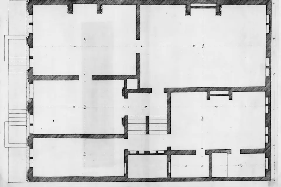
Mark the mounting center, pick and place points and complete travel path on a plan, then add machine doors, conveyors, guards, columns, racks and operator positions. Coverage checks must include detours and obstacle avoidance along the route; the straight-line distance between picking and placing points alone cannot determine arm length.
03Why more reach is not always better
- Greater load moment: the same workpiece produces a larger bending moment farther from the rotation center. Columns, bases, joints, bearings and foundation fixings may need larger specifications, increasing cost.
- Greater operating inertia: long arms are harder to start, stop and rotate accurately, affecting precise placement, assembly and machine loading.
- Stability may decrease: When the working radius is too large, the shaking of the end-effector tooling and the workpiece will be more obvious, especially when the fixture is heavy, the center of gravity is offset, or the cycle time is fast.
- Increased space occupied: Coverage is larger, taking up more workshop space and increasing overlap with personnel passages, forklift routes, adjacent equipment, and material racks.
- Greater interference risk: a larger swept area can intersect machine enclosures, conveyors, columns, pipes, cable trays and other tooling.
04Determining the required radius
1. Measure pickup and placement locations
Measure all pick and place points from the same equipment mounting-center datum, recording column, rail or suspension locations. For multiple points, check both the farthest effective working point and the folding-arm and gripper approach space at the nearest point.
2. Confirm the workpiece movement path
Include detours, lifting/lowering, rotation and waiting for positioning in the transfer path. For large workpieces, add the swept envelope of the workpiece outline and verify that the entire movement remains within usable coverage.
3. Check clearance from equipment, people and structures
Machine tool doors, protective covers, conveyor lines, material frames, shelves, columns, walls, pipelines, personnel passages, etc. should be inspected on site. When the working radius is too large, the fixture and workpiece may enter undesirable areas. If necessary, mechanical limits should be set or the installation position should be adjusted.
4. Include workpiece and tooling weight
Total load includes the workpiece, gripper, suction-cup frame, cylinders, rotary mechanism, handles and connections. Radius and total load jointly affect structural stiffness and balancing configuration. Equipment selection must include gripper weight.
5. Check lifting stroke and operator position
Check operator positions, visibility and walking routes through picking, moving and placing. Avoid forcing operators to lean over because of insufficient reach or adding unnecessary detours because of excessive reach. Check lifting stroke against pick and place heights and obstacle-clearance needs at the same time.
6. Allow for variation and clearance
Set allowances for site dimensional tolerances, workpiece placement variation, gripper length and obstacle clearance, and include them in structural and interference checks. Provide space sufficient to cover these variations without enlarging the radius arbitrarily.
05Simple estimation example
The following example only illustrates how allowances are composed. A workstation has a horizontal distance of 2.4m between pick and place points. This cannot be treated directly as a 2.4m working radius; both points must be checked relative to the mounting center. The path must clear the bin edge and conveyor guard, preserve an operator position, account for 100–200mm of workpiece placement variation, and allow gripper rotation and fine adjustment.
If checking the mounting point and path establishes a basic radial requirement of 2.4m, an illustrative estimate may add 0.2m for operating clearance, 0.1–0.2m for placement variation and 0.2m as a safety allowance, giving an effective radius requirement of approximately 2.9–3.0m. This result does not directly imply a 3.5m or longer arm. Aisles, columns, machine enclosures and adjacent stations beyond 3.0m still require checking. Complete the structural selection using rotation angle, gripper length and the full path.
06How installation type affects reach
- Column-mounted: suited to a fixed workstation or nearby stations. Radius depends on column location, foundation fixing and rotation range. A distant column increases reach demand; one too close can interfere with the workpiece or operator.
- Mobile: check floor level, base stability and brakes. Relocate the equipment without a load, then secure the base at the workstation as specified before loaded operation. Do not simply extend the arm to cover more areas.
- Overhead-mounted: suited to restricted floor space or coverage from above. Verify the capacity of beams, steelwork and suspension supports, and clearance from pipes, lighting and cable trays.
- Rail-mounted: Rails extend coverage across multiple stations while controlling individual arm length. Check rail length, suspension points, trolley resistance and end stops when selecting the system.
- Jib or articulated-jib cranes: provide rotary handling within a defined area. Check rotation radius, lifting points, tooling swing and surrounding clearance.
07Typical applications
- Machine tool loading and unloading: The radius should cover the material frame, machine tool door and clamping position, while avoiding the machine tool shell and operation panel. If it is too long, it will affect the positioning feel. If it is too short, the person will need to lean over to place the parts.
- Carton handling: Check starting/stopping effort and rotational inertia against pallet positions and cycle time. For multiple pallet positions, compare rail-mounted and column-layout options before setting the individual arm length.
- Automotive assembly: coordinate reach with tooling turning, rotation and positioning. Check orientation accuracy and clearance from the vehicle body, fixtures and operators.
- Sheet handling: large sheets have a wide swept envelope even at low weight. Allow clearance for their corners during rotation and include vacuum-tooling length in the radius assessment.
- Roll handling: horizontal lifting, turning or axial alignment may be required. The tooling must approach the workpiece center of gravity reliably, with room for fine adjustment at placement.
08Site reach checklist
| Item | On-site data required | Purpose of check |
|---|---|---|
| Pickup location | Pickup coordinates, bin dimensions and pickup height | Determine whether the equipment can successfully approach the workpiece |
| Placement location | Placement coordinates, equipment/fixture dimensions and placement height | Determine the maximum effective operating range |
| Horizontal handling distance | Horizontal distance of pick and place points, installation center position | Preliminary estimate of working radius |
| Workpiece parameters | Weight, dimensions, center of gravity, surface condition | Determine the load moment and fixture form |
| Tooling parameters | Tooling self-weight, length, opening/closing method and rotation requirements | Assess end-tooling extension and operating clearance |
| Travel path | Straight travel, detours and turning requirements | Determine actual coverage and risk of interference |
| Surrounding obstacles | Positions of columns, shelves, machine tools, conveyor lines, and guardrails | Determine travel-limit or layout adjustments |
| Operating position | Personnel standing position, line of sight, passage width | Determine operating comfort and safe space |
| Lifting stroke | Pick and place height difference, obstacle clearance height, tooling height | Determine whether the lifting stroke matches |
| Safety allowance | Placement error, avoidance space, maintenance space | Determine the necessary reach allowance |
09Site information for equipment selection
Selection data includes the site plan and proposed mounting position; pick and place coordinates and heights; workpiece weight/dimensions/center of gravity/surface condition; cycle time and daily frequency; gripping method; flipping and rotation movements; obstacles, personnel aisles, air supply and safety requirements.
Where full drawings are unavailable, build the layout using site photos, videos, hand-drawn dimensioned sketches and key measurements. For complex stations, mark machine-door opening envelopes, conveyor heights, bin dimensions, rack locations and distances to columns or walls for coverage and interference checks.