- Before installation, verify the workpieces, movements, space, mounting type, foundation, air supply and safety areas.
- Use workpiece weight, dimensions, material, surface and center of gravity to select load capacity and tooling, then check the technical design and equipment nameplate.
- Define pickup and placement locations and the complete handling method to establish working radius and lifting stroke.
- Site information should cover workpieces, pick and place points, the complete motion sequence, mounting foundations, utility interfaces and surrounding layout for structural and gripper assessment.
Prepare for pneumatic industrial manipulator installation from the actual handling task, organizing workpiece information, motion paths, site space and utilities in sequence. Link measurements and site photos to the design documentation to check equipment placement, gripper integration and the full pick-and-place process.
01Workpiece and tooling selection data
Record workpiece weight, overall dimensions, material, surface condition, center of gravity and permitted load-bearing locations, identifying risks of deformation, scratching or dropping. Use this information to select jaws, suction cups, internal-expansion or wraparound grippers and to check contact surfaces and operating orientations.
For multiple variants, list the largest, smallest and common variants separately. Verify loads and configurations using the equipment nameplate and technical documentation; do not estimate equipment capacity from appearance or experience.
02Pickup, placement and the complete movement sequence
Describe movements and cycle time in the order of picking, lifting, transfer, orientation adjustment and placement. Record the position of each pick and place point, lifting height, rotation angle, horizontal travel and flip angle. Explain insertion/location and tooling integration requirements so the working range reflects actual operation.
Provide a video of the complete task and identify operator positions, handle operating directions, placement accuracy and cycle-time requirements. Assess manipulator orientation and clearance at every key position so that coverage of the endpoints also permits the intermediate movements.
03Site space and mounting type
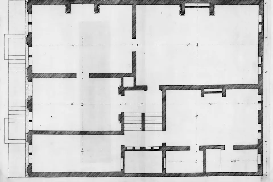
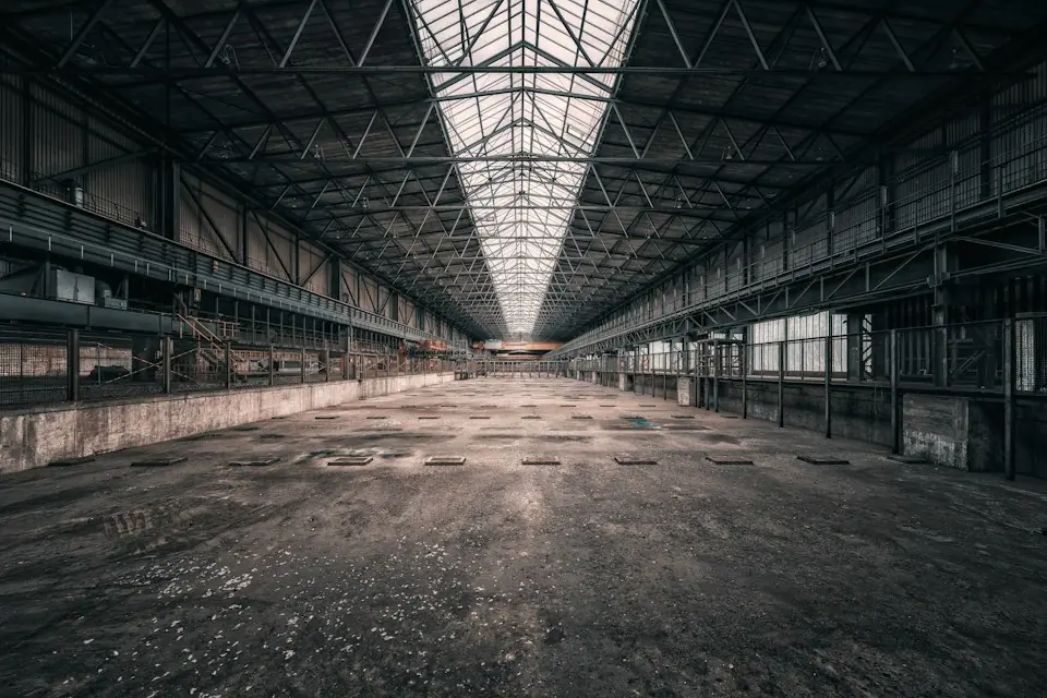
Site measurements should locate equipment, columns, guards, racks, machine doors, services and aisles and record clearances along the workpiece path. Plan mounting points together with operator positions, equipment motion, material flow and maintenance space.
Check floor flatness, load-bearing conditions and whether drilling is permitted. For steel platforms, mezzanines or special structures, provide structural information for qualified personnel to verify installation conditions.
04Foundations, air supply and interference
Record air-connection location, pressure, flow, pipe diameter, cleanliness and filter/regulator configuration, checking each against the equipment's technical requirements. Finalize utility interfaces and piping routes before installation.
Check the installation floor for cracks, hollow areas, settlement and other abnormalities. Check brackets, cable trays and services against the equipment motion range. Include robot, AGV, forklift and pedestrian routes in dynamic interference checks.
05Operators, safety areas and installation records
Define operator positions, pickup and placement postures, two-hand requirements, shared work areas and exposure to heat, sharp edges, rotating equipment or presses. Plan safety areas to avoid overlaps between slewing zones, pedestrian aisles, forklift routes and material storage. For custom grippers, turning mechanisms and vacuum tooling, establish release conditions, air-loss protection, drop prevention, travel limits and buffers.
Installation information should include site dimensions, workpiece drawings or photos, a complete-motion video, foundation and air-supply details, the site contact and site-entry requirements. Associate the information with the specific station for installation, commissioning and training.
06Pre-installation site checklist
| Item | Required checks | Information to provide | Precautions |
|---|---|---|---|
| Workpiece Information | Weight, size, material, surface condition, center of gravity position | Workpiece drawings, photos, weight range, specification list | Check load capacity and tooling parameters against the technical design and nameplate |
| Handling movements | Pickup/placement locations, lifting, rotation, turning and positioning | Movement video, workstation sketch and cycle-time requirements | Check the complete path, including intermediate movements |
| Site space | Nearby equipment, aisles, racks, services and guards | On-site photos, floor plan, key dimensions | Focus on checking the operating radius and lifting stroke |
| Mounting type | Floor, column, suspended or rail-mounted arrangements | Mounting location and overhead or floor structural information | Different installation methods correspond to different installation conditions |
| Foundation | Floor flatness, thickness, load-bearing capacity, whether drilling is allowed | Floor information, base plans, site restrictions | Identify trenches, mezzanines or hollow floor areas in advance |
| Air supply conditions | Pressure, flow, interface, pipe diameter, cleanliness | Air connection location, piping photographs and supply parameters | Check supply parameters against the technical design and nameplate |
| Equipment interference | Relationship with machine tools, conveyor lines, robots, and forklift channels | Site layout, equipment height, operating range | Static and dynamic interference need to be considered |
| Operator positions | Personnel position, operating direction, pick-and-place attitude | Photos of operating procedures and personnel positions | Effort saving, field of view and safe distance should be taken into consideration |
| Safety areas | Slewing, tooling-motion and workpiece travel zones | Aisle planning and safety requirements | Avoid overlapping with personnel and logistics channels |
| Installation records | Drawings, photos, videos, site dimensions, working condition descriptions | Complete project package | Complete information supports accurate configuration assessment |