- Sinking, drift, binding, rebound and increased operating effort all require the fault investigation procedure. Do not continue using the equipment on the assumption that these are normal running-in effects.
- First, stop operation, unload safely and secure the area. Then inspect the air supply, vacuum system, mechanical structure, tooling and safety functions.
- For sinking, check air supply, balancing, seals and load; for drift, check damping, installation security and pressure; for binding, check bearings, tracks, foreign objects and tooling interference.
- For continued sinking under load, unreliable gripping or release, emergency-stop failure or burst hoses, stop use immediately and tag out the equipment.
Continuing to operate handling equipment with sinking, drift, binding or unstable motion may cause workpieces to slip, tooling collisions, personal injury and equipment damage. First control site risks, then investigate possible causes according to the symptom. The table at the end links symptoms, causes, inspection methods and recommended actions to support preliminary diagnosis.
01Recognizing sinking, drift and binding
- Abnormal sinking: downward movement without a lowering command, either unloaded or under load, or continued slow descent after stopping. The gripped workpiece may gradually descend, or the arm may fail to hold its position.
- Drift: the equipment moves by itself in a slewing, translation or lifting direction without being pushed or after a light touch, and cannot maintain a stable stopped position.
- Binding: increased resistance at a particular position, interrupted movement, jamming, unusual noise or failure to return.
- Rebound and impact: sudden rebound, vibration, impact or rapid unintended motion when movement stops.
- Increased operating effort: lifting, slewing and translation become harder and less smooth than usual.
If these symptoms occur, record the location, direction and operating conditions and follow the fault procedure. Do not simply dismiss them as normal running-in or isolated events.
02Control the risk before troubleshooting
Immediately stop the current handling motion when an abnormality occurs. Under safe conditions, return the workpiece to a support surface, fixture or pallet rather than leaving it suspended. If the equipment remains controllable, move it slowly to a safe position; do not pull sharply or force it back. Once the workpiece is safely placed, notify maintenance personnel or the equipment supervisor.
When pneumatic equipment behaves abnormally, maintain or stabilize the air supply to avoid loss of balance from a sudden air cut-off. If there is substantial leakage, uncontrolled motion, failure of the tooling to release or a risk to personnel, apply emergency-stop, air-isolation and exclusion measures in accordance with the site's safety procedures. Do not repeatedly test a fault under load.
03Sinking: causes and checks
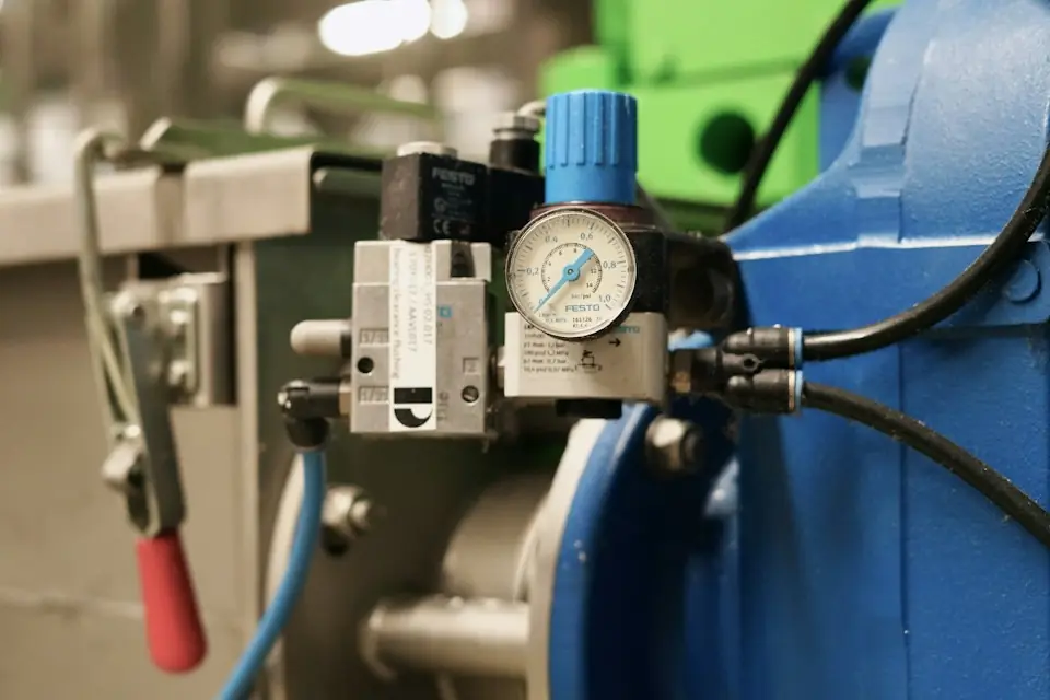
To investigate sinking, first check that supply pressure meets the equipment requirements, then check the filter-regulator setting and gauge fluctuations. Inadequate air supply reduces balancing force and makes sinking more likely under load. Next check the balancing system, seals and any load changes.
Check pressure retention along hoses, fittings and valve assemblies, looking for ageing, kinks, abrasion, loose fittings and poor sealing. For cylinder-based balancing systems, also check cylinder-seal wear, internal leakage and valve faults. After changing the workpiece, tooling or suction-cup frame, or adding accessories, recheck whether the actual load exceeds the original setting range.
04Drift: causes and checks
Classify drift by its direction first. For vertical drift, focus on balance adjustment, load changes and pressure stability. For horizontal slewing or rail-travel drift, focus on joint damping, brake wear, rail and floor level, and loose columns or bases.
An abnormal installation condition may change the forces acting on the equipment, causing sideways movement or self-travel. The equipment supervisor should inspect base bolts, connecting flanges, arm joints, rail suspension points and end stops for looseness, deformation and increasing connection clearance, and verify the supporting foundation.
05Binding and increased operating effort: causes and checks
First distinguish binding at a particular location from resistance throughout the stroke. For binding at a fixed location, inspect for foreign objects, deformation, impact marks and stop interference. If movement is heavy throughout the stroke, check the air supply, balancing system, joint lubrication, bearing resistance and rail cleanliness. Other possible causes include dry or worn pins and bushings, damaged rollers, mechanical deformation, incorrect lubrication and interference within the tooling.
Worn or loose jaws, links, pins, springs or stops may cause unsynchronized motion, incomplete reset or workpiece interference. Inspect the relevant mechanism. Do not overcome binding by applying greater operating force, as this may deform the tooling or damage the workpiece.
06Rebound, impact and unstable motion
For rebound, impacts or erratic speed, check motion speed, air supply, flow control and the load's centre of gravity together. Pressure fluctuations affect lifting and tooling motion; incorrect flow-control settings may make cylinders move too quickly, while rapid manual pushing or pulling may cause inertial swing.
Even when workpiece weight is unchanged, a different gripping point, an eccentric workpiece or uneven suction-cup placement may cause impacts and rebound during movement and stopping. If accompanied by substantial noise or vibration, or if the equipment cannot stop stably after an emergency stop, withdraw it from service immediately. Maintenance personnel should inspect the brakes, valves, cylinders, joints and travel-limit mechanisms.
07Vacuum-gripping faults
Vacuum faults can be identified during build-up, retention and release: prolonged pickup time, low gauge readings, slipping workpieces, incomplete release and local leakage. Investigate leaking, hardened or cracked suction cups; rough or oily workpieces; insufficient air supply to the generator; blocked filters; and vacuum-line leaks.
First remove dust and debris from the contact surface and inspect the cups for hardening, curled edges or cracks. Replace cups if cleaning does not restore performance. For rough, porous or deformed workpieces, reassess the suitability of the original tooling; do not compensate for inadequate suction by increasing operating speed. Also investigate leaks at cup mounts, vacuum hoses, push-in fittings, distribution blocks and valve seals, using leak sounds, gauge changes and sectional blanking tests to locate them.
08Symptoms, causes, checks and actions
| Symptom | Possible Causes | Inspection method | Recommended Action |
|---|---|---|---|
| Slow descent under load | Insufficient air pressure, air hose leakage, cylinder seal wear, and load exceeding setting | Check the pressure gauge, listen for air leakage, and check the weight of the workpiece | Stabilize the compressed-air supply, repair air leakage points, and reconfirm load and balance |
| Descent without a load | Changed balance settings, valve faults or cylinder internal leakage | Test unloaded position holding and observe pressure retention | Take it out of service and have the valve block and cylinder seals checked by maintenance personnel |
| Horizontal drift | Insufficient joint damping, uneven track, loose installation | Check joints, rails, anchor bolts and levels | Adjust damping, tighten mounting points, review track and foundation |
| Binding at one position | Foreign objects, faulty travel limits or structural deformation | Inspect the binding location, impact marks and travel limits | Remove foreign matter, repair the limit, and correct the structure if necessary |
| Increased effort throughout the stroke | Insufficient lubrication, bearing wear, track contamination, abnormal air pressure | Check lubrication, rollers, bearings, air supply pressure | Clean and lubricate, replace worn parts, and restore compressed-air supply parameters |
| Rebound or impact when stopping | Pressure fluctuations, incorrect flow-control settings, rapid operation or shifted center of gravity | Observe speed and inspect the flow-control valve and load orientation | Adjust flow control, correct operating technique and improve gripping locations |
| Unstable vacuum holding | The suction cup is leaking, the workpiece is rough, the filter is clogged, and the vacuum is insufficient. | Look at the vacuum gauge and check the suction cup and filter | Replace the suction cup, clean the filter, and check the vacuum pipeline |
| Incomplete or difficult tooling release | Air path blockage, spring fatigue, mechanism interference, valve group abnormality | Test tooling opening, closing and return without a load | Clean the pneumatic line, replace the spring, check the valve group and interference |
| Abnormal motion after an emergency stop | Brake or safety-circuit fault, or residual pneumatic pressure | Verification of emergency stop function under low-risk conditions | Stop use immediately and have qualified personnel inspect the safety system |
09Conditions requiring immediate withdrawal from service
Stop using the equipment immediately and do not continue loaded operation if it sinks uncontrollably; tooling cannot grip or release reliably; inadequate vacuum allows a workpiece to slip; joints are visibly loose, unstable or noisy; emergency stops or brakes fail; hoses burst, leak severely or cause violent gauge fluctuations; travel limits or drop prevention fail; or tooling deforms, welds crack or connecting bolts loosen.
10Operator checks and specialist maintenance
Tasks operators may perform: stop using the equipment and lower the workpiece safely; record the location, direction and conditions of the abnormality; observe the air-pressure gauge and any dirty or damaged suction cups; and check for excessive workpiece weight, off-centre loading or abnormal placement. Tell maintenance personnel when the issue occurred, the load involved and the operating sequence.
Tasks for maintenance personnel or the equipment manufacturer: balance-parameter adjustment; valve and cylinder dismantling; cylinder-seal repair; replacement of critical pneumatic components; flow-control and brake adjustment; joint-bearing removal and installation; rail and structural alignment; safety-circuit repair; and verification of tooling load capacity. Do not modify custom-tooling circuits or valve assemblies, or remove safety interlocks, solely on the basis of on-site experience.