- Abnormal air hoses and fittings may cause pressure loss and changes in control response. Investigate them in relation to motion, clamping, vacuum and load-balancing conditions.
- Before inspection, unload safely, stop the equipment, isolate the air supply and release residual pressure. Never dismantle components under load or pressure.
- Leaks can reduce pressure and slow motion, causing unstable gripping, dropped workpieces, inadequate vacuum, abnormal balancing and increased energy use.
- The manufacturer or qualified personnel should handle safety valves, pneumatic control modules and balancing systems. Do not dismantle these critical components independently on site.
When pneumatic industrial manipulators, pneumatic balancing hoists, vacuum lifters or their tooling leak air, observe both equipment motion and workpiece retention. If clamping, vacuum gripping or load balance is affected, unload safely and shut down before arranging inspection. Critical control components must be handled by the manufacturer or qualified personnel.
01Effects of leaking hoses and loose fittings
- Reduced supply pressure: where leakage reduces the effective air supply, the equipment may be difficult to start, lack force or move more slowly.
- Slower motion response: affected actuator response and lifting continuity may extend machine-loading, assembly or transfer cycles.
- Unstable gripping: pressure loss reduces clamping force. Heavy, oily or off-center workpieces may slip, tilt or fall.
- Unstable vacuum gripping: leaks in the supply or vacuum piping may cause inadequate suction, declining retention pressure and alarms, and may lead to a dropped workpiece in severe cases.
- Abnormal load balance: leaks in the balancing circuit may cause the workpiece to rise, sink, fail to hold position stably or require more operating effort.
- Protective-function faults: abnormal pressure-switch, vacuum-sensor, limit-valve or safety-valve signals can cause false alarms, unnecessary stops, frequent protective responses or failed protection.
- Increased energy and maintenance demands: continuous compressor replenishment may increase energy consumption, while continued abnormal operation can add to maintenance demands on valves, seals, cylinders and vacuum generators.
02Record, unload, inspect and retest
- Step one: record the abnormal condition: record symptoms such as slow motion, vibration, unstable holding position, weak clamping or insufficient suction, together with the workstation, motion and time of occurrence.
- Step two: unload safely and shut down: place the workpiece in a stable position and confirm that the tooling has released it or that the load is safely supported. Then stop the equipment, shut off the air supply and release residual pressure. Never dismantle components under load or pressure.
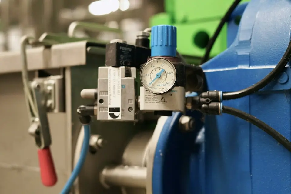
- Step three: check air-supply information: compare fault-time pressure records with the nameplate, manual or design requirements. Investigate the main supply, filter-regulator and branches. Qualified personnel must perform any pressure-on checks under the equipment procedure; no components may be dismantled while pressurized.
- Step four: inspect piping and fittings: after unloading, shutdown and release of residual pressure, inspect from the air inlet through valves and actuators to the tooling end for ageing, flattening, kinks and rupture, and for loose, disconnected or poorly sealed fittings.
- Step five: inspect the tooling end: check suction cups for ageing, deformation and cuts, and workpiece surfaces for roughness, holes, oil and dust. For mechanical gripping, also check jaws, cylinders, stops and connections.
- Step six: reset and carry out a trial run: after ordinary leak points have been repaired, retest without a load or under low-risk conditions in accordance with the equipment procedure. Resume production gradually once motion, pressure, suction and alarm states are normal.
03Pneumatic fault checklist
| Symptom | Possible Causes | Inspection method | Recommended Action |
|---|---|---|---|
| Sluggish motion | Hose leaks, insufficient supply pressure or blocked filters | Observe the pressure gauge, listen for air leakage, and check the pipelines | Repair leaks and clean or replace filter elements |
| Unstable position holding | Balancing faults, pressure fluctuations or valve faults | Test position holding without a load and under load using the prescribed procedure | Stop and inspect; contact the manufacturer for balancing-system faults |
| Unstable gripping | Loose fittings, insufficient clamping-cylinder pressure or worn jaws | Check the fixture air path, clamping action and mechanical connections | Secure fittings, replace worn parts and involve the manufacturer where required |
| Insufficient vacuum holding | Vacuum leakage, aging suction cup, and workpiece surface not suitable for vacuum gripping | Check vacuum gauge, suction cup edge and workpiece surface | Replace the suction cup, clean the surface, and review the vacuum gripping plan |
| Frequent alarms or unexpected shutdowns | Pressure-switch or safety-valve faults; circuit pressure fluctuations | View alarm location and pressure changes | Have qualified personnel inspect safety components; do not dismantle independently |
| Increased air consumption | Long-term air leakage in pipelines and poor joint sealing | With motion stopped, qualified personnel may listen or use leak-detection fluid under the equipment’s pressure-on inspection procedure | Replace pneumatic tubing, fittings or seals |
| Workpiece floats or sinks | Balancing-circuit leakage, changed load or incorrect adjustment | Observe load position holding and rise/descent behavior | Stop using it and contact the manufacturer to check the load balancing system. |
04Daily inspection and maintenance records
During daily checks, observe hose wear, bending, ageing and compression; record unusual leakage sounds during operation or pressure retention; and check the pressure gauge, vacuum gauge, filter-regulator and alarm records. Physical checks for loose fittings and hose tension must be performed after unloading, shutdown and depressurization. Secure frequently moving hoses or those near sharp edges and protect them from abrasion as specified. Periodically inspect suction-cup edges, elasticity and sealing faces, as well as clamping mechanisms, stops, connecting bolts and cylinders. Include pressures, leak locations, fitting or cup replacement and abnormal alarms in the equipment log.