
Application cases · Workpiece turning
Disc and Flange Turning, Loading and Unloading Application
A pneumatic industrial manipulator with custom clamping and turning tooling picks disc- and flange-shaped metal workpieces from inside equipment, withdraws, turns and places them, connecting loading and unloading with orientation changes between processes.
- Equipment arrangement
- Pneumatic industrial manipulator
- Tooling
- Custom clamping and turning tooling
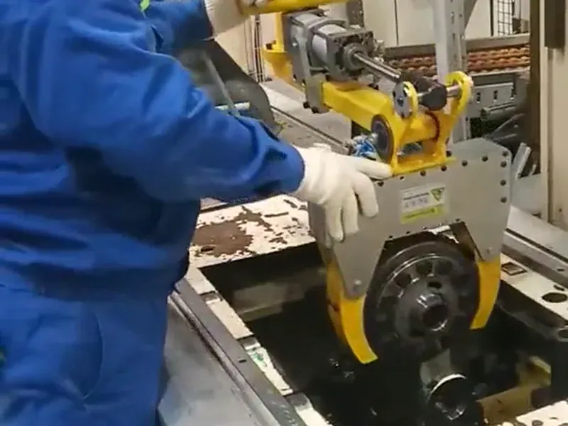 Workpiece turningWatch on-site video
On-site video
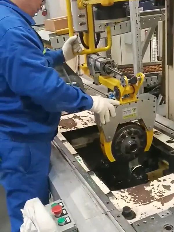 Watch the full video on WeChat Channels
On-site footage
A pneumatic industrial manipulator with custom clamping and turning tooling picks disc- and flange-shaped metal workpieces from inside equipment, withdraws, turns and places them, connecting loading and unloading with orientation changes between processes.
Open WeChat Channels ↗Application overview
Loading and unloading disc- and flange-shaped metal workpieces requires consideration of gripping positions, machine openings and pick-and-place orientations. AUREK combines a pneumatic industrial manipulator with custom clamping and turning tooling. The manipulator carries the handling load while the operator guides the workpiece out of the machine and adjusts its orientation, connecting gripping, transfer, turning and placement in one operating sequence.
System configuration
| Workpiece | Disc-, flange- and housing-shaped metal workpieces |
|---|---|
| Equipment arrangement | Pneumatic industrial manipulator |
| Tooling | Custom clamping and turning tooling |
| Main motions | Alignment, clamping, lifting, withdrawal, turning and placement |
| Operation | The operator guides workpiece movement and orientation changes using an operating handle |
| Workstations | Machine loading and unloading, assembly assistance and orientation changes between processes |
Configuration features
- Clamping and turning functions are combined in the end tooling. The workpiece changes orientation while continuously gripped, reducing changes of hand position and secondary manual lifting.
- The manipulator carries the handling load while the operator guides the workpiece using a handle, reducing direct manual support at the machine opening.
- The tooling is arranged around the workpiece's gripping positions and the machine opening, connecting pickup inside the machine with placement outside it.
Operating sequence
- Guide the tooling into the machine opening, align with the workpiece gripping references, clamp and check contact between the workpiece and tooling.
- Slowly lift the workpiece clear of its original support, then withdraw it along the pickup path, clearing the worktop and surrounding mechanisms.
- Move the workpiece to a position with sufficient turning space. Maintain the grip and use the turning mechanism to reach the orientation required for the next process.
- Align with the target fixture and lower slowly. Release the tooling after the fixture stably supports the workpiece, then withdraw and return to the pickup position.
Selection and configuration
- Profile-matched contact components or protective pads can be selected for the workpiece shape, accounting for available gripping positions and surface requirements.
- The turning mechanism can be selected for the workpiece center of gravity and target orientation, with suitable travel and positioning methods to connect loading and unloading motions.
- Adjustable clamping structures or quick-change tooling can be selected for a family of workpieces, with contact components configured for the size range to support workstation changeover.
Frequently asked questions
Does the workpiece need to be gripped again for turning?
The tooling combines clamping and orientation adjustment. The workpiece remains continuously gripped during turning, and the tooling is released after placement in the target fixture.
How are pickup inside the machine and turning arranged?
First clamp and lift the workpiece, withdraw it through the machine opening, then adjust its orientation where there is sufficient turning space before alignment and placement. The tooling profile and motion path are arranged around the machine opening and surrounding structures.
More cases
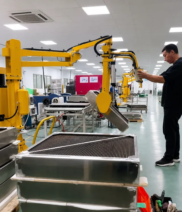 Metal workpiece turningOn-site videoLarge Metal Workpiece Handling and Turning ApplicationA pneumatic industrial manipulator with custom clamping and turning tooling carries the lifting load of large metal workpieces and turns and positions them while maintaining the grip. One operator guides pick-and-place and orientation changes.
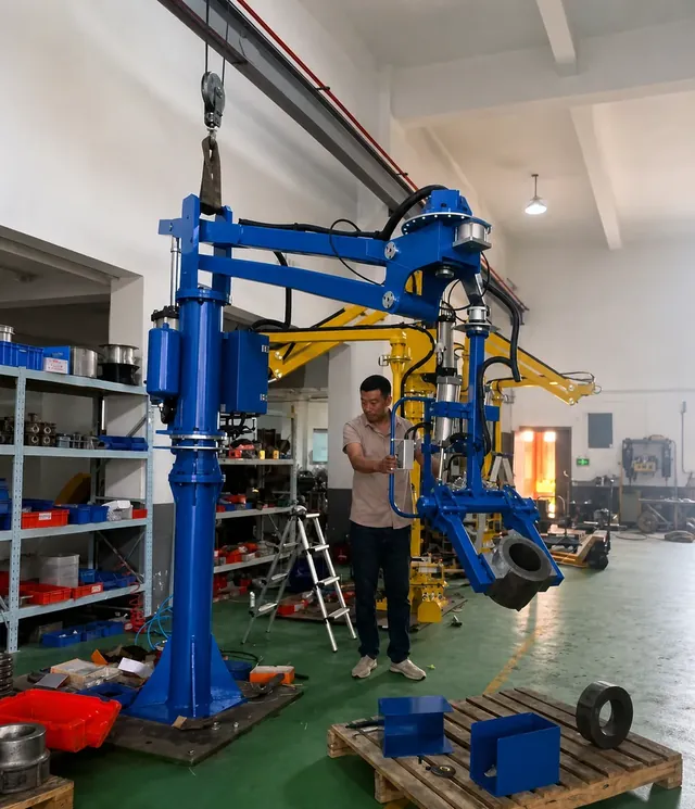 Ring turningOn-site videoRing Workpiece Handling and Turning ApplicationA pneumatic industrial manipulator with dedicated ring tooling lifts, transfers and turns ring-shaped workpieces while maintaining the grip. One operator guides orientation and position, reducing direct manual support and changes of hand position.
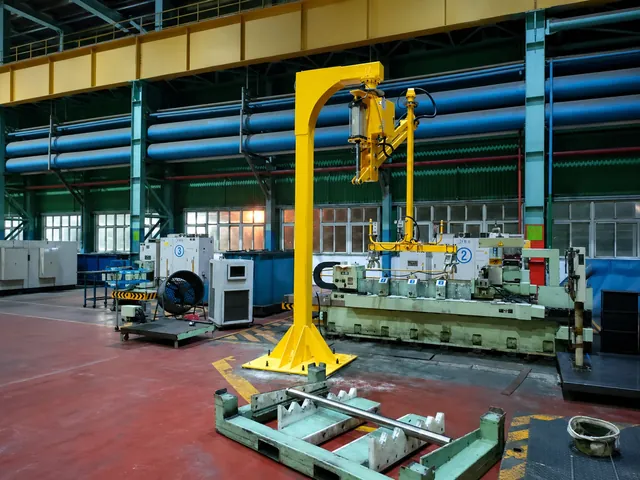 Work roll handlingWork Roll Handling for Grinder Loading and UnloadingAn overhead-mounted pneumatic industrial manipulator with adjustable tooling assists with gripping, lifting and loading or unloading work rolls at grinding equipment, reducing floor occupancy. The operator guides the roll toward the fixture and adjusts its placement position.
Submit your requirements, get a technical proposal
Share the workpiece name, weight per workpiece, dimensions and pick-and-place motions, and an engineer will recommend a manipulator arrangement, working range and end tooling. Drawings and site photographs can be sent by email or WeChat.
